Section 04: EXHAUST AND AFTERTREATMENT SYSTEM
PA1593
12
CAUTION
It must be checked if there are cracks around
the area of the filter cover. No cracks in the
material are allowed. If there are cracks in the
housing, the entire Supply Module must be
replaced! If there are cracks in the filter cover,
the filter cover must be replaced.
MAINTENANCE
Replace pump assembly filter element every
150,000 miles or every three years, whichever
comes first.
6.
AFTERTREATMENT FUEL INJECTOR
Proper functioning of the aftertreatment fuel
injector a.k.a. aftertreatment hydrocarbon
injector (AHI) is required in order to obtain
efficient regeneration process of the DPF.
Clogged aftertreatment fuel injector will result in
clogged DPF.
In addition to the activation of the CHECK
telltale, emission of diagnostic troubleshooting
codes (DTC) by the engine ECM (MID128) will
indicate malfunction of the aftertreatment system
and/or aftertreatment fuel injector. DTC may be
accessed through the Driver Information
Display. Select DIAGNOSTICS menu then
FAULT DIAGNOSTICS and ENGINE ECU
submenus.
Check status of the aftertreatment system
through the Driver Information Display. Select
AFTERTREATMENT menu then ATS STATUS.
Then check the DPF soot level with SOOT
LEVEL GAUGE.
6.1 REPLACEMENT
1. Remove fastener and p-clamp securing the
line to the mounting bracket on the diffuser
pipe.
WARNING
Fuel leaked or spilled onto hot surfaces or
electrical components can cause a fire and
result in component damage and serious
personal injury.
2. Disconnect the line from the aftertreatment
hydrocarbon injector fitting. Collect any
residual fuel that might be in the line in a
suitable container.
CAUTION
Do not kink the line. Kinking the line may
result in leakage.
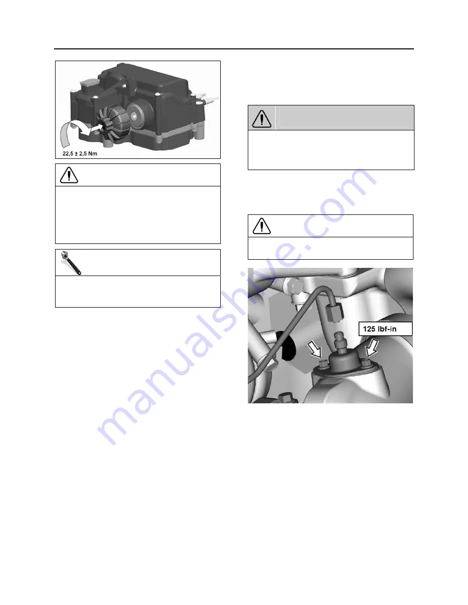
FIGURE 9: AFTERTREATMENT FUEL INJECTOR
3. Remove the aftertreatment hydrocarbon
injector mounting fasteners. Remove the
aftertreatment hydrocarbon injector from the
diffuser pipe (which attaches to the
turbocharger outlet).
4. Clean the sealing surface on the diffuser pipe
before mounting the aftertreatment
hydrocarbon injector.
5. Install the aftertreatment hydrocarbon injector
onto the diffuser pipe (which attaches to the
turbocharger outlet). Tighten the fasteners to
125 lbf-in
.
Summary of Contents for X3-45 2016
Page 4: ......
Page 16: ...Section 00 GENERAL INFORMATION PA1593 12 FIGURE 12 METRIC US STANDARD CONVERSION TABLE 00005...
Page 17: ...Section 00 GENERAL INFORMATION 13 PA1593 FIGURE 13 CONVERSION CHART 00006...
Page 18: ......
Page 26: ......
Page 58: ......
Page 72: ...Section 04 EXHAUST AND AFTERTREATMENT SYSTEM PA1593 14 7 TORQUE SPECIFICATIONS...
Page 73: ...SECTION 04 EXHAUST AND AFTERTREATMENT SYSTEM PA1593 15...
Page 74: ...Section 04 EXHAUST AND AFTERTREATMENT SYSTEM PA1593 16...
Page 76: ......
Page 96: ......
Page 134: ......
Page 176: ...SECTION 06B ELECTRICAL 38 overcurrent working Circuit 306 shorted to ground...
Page 180: ......
Page 202: ......
Page 205: ...Section 09 PROPELLER SHAFT PA1593 3 FIGURE 1 PROPELLER SHAFT ASSEMBLY 09002...
Page 256: ......
Page 268: ......
Page 295: ...SECTION 16 SUSPENSION PA1593 9 2 5 TORQUE SPECIFICATIONS...
Page 296: ...Section 16 SUSPENSION PA1593 10...
Page 297: ...Section 16 SUSPENSION PA1593 11...
Page 314: ......
Page 380: ......
Page 388: ......
Page 413: ...Section 22 HEATING AND AIR CONDITIONING PA1593 15 FIGURE 18 REFRIGERANT CIRCUIT CENTRAL SYSTEM...
Page 433: ...Section 22 HEATING AND AIR CONDITIONING PA1593 35 FIGURE 36 CENTRAL HEATING SYSTEM COMPONENTS...


