Section 05: COOLING SYSTEM
Section 05 Updated Sept.2016
X3-45 Commuter PA1593 DOB 2400-2489
3
1. DESCRIPTION
A radiator and thermo-modulated fan are used
to effectively dissipate the heat generated by the
engine. A centrifugal-type water pump is used to
circulate the engine coolant.
One full blocking-type thermostat is used in the
water outlet passage to control the flow of
coolant, providing fast engine warm-up and
regulating coolant temperature.
The engine coolant is drawn from the lower
portion of the radiator by the water pump and is
forced through the transmission cooler before
going through the oil cooler and into the cylinder
block.
From the cylinder block, the coolant passes up
through the cylinder head and, when the engine
is at normal operating temperature, it goes
through the thermostat housing and into the
upper portion of the radiator. The coolant then
passes through a series of tubes where its heat
is dissipated by air streams created by the
revolving fan and the motion of the vehicle.
Upon starting a cold engine or when the coolant
is below normal operating temperature, the
closed thermostat directs coolant flow from the
thermostat housing through the by-pass tube to
the water pump. Coolant is recirculated through
the engine to aid engine warm up.
When the thermostat opening temperature is
reached, coolant flow is divided between the
radiator inlet and the by-pass tube. When the
thermostat is completely open, all of the coolant
flow is to the radiator inlet.
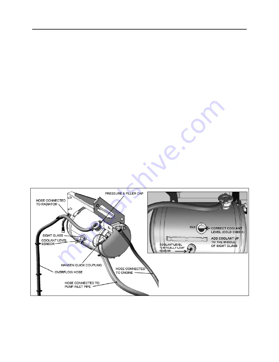
The cooling system is filled through a pressure
& filler cap on the surge tank (Fig. 1), the cap is
also used to maintain pressure within the
system. When system exceeds normal pressure
rating (14 psi - 96.53 kPa), the cap releases air
and if necessary, coolant through the overflow
tube (Fig. 1). The thermostat is located in the
housing bolted to the engine on the L.H. side.
The engine cooling system also provides hot
coolant fluid for the vehicle heating system. Refer
to section 22,
"”HEATING AND AIR
CONDITIONING"
in this manual for information
relating to heating system water circulation.
FIGURE 1: COOLANT SURGE TANK
05132
Summary of Contents for X3-45 2016
Page 4: ......
Page 16: ...Section 00 GENERAL INFORMATION PA1593 12 FIGURE 12 METRIC US STANDARD CONVERSION TABLE 00005...
Page 17: ...Section 00 GENERAL INFORMATION 13 PA1593 FIGURE 13 CONVERSION CHART 00006...
Page 18: ......
Page 26: ......
Page 58: ......
Page 72: ...Section 04 EXHAUST AND AFTERTREATMENT SYSTEM PA1593 14 7 TORQUE SPECIFICATIONS...
Page 73: ...SECTION 04 EXHAUST AND AFTERTREATMENT SYSTEM PA1593 15...
Page 74: ...Section 04 EXHAUST AND AFTERTREATMENT SYSTEM PA1593 16...
Page 76: ......
Page 96: ......
Page 134: ......
Page 176: ...SECTION 06B ELECTRICAL 38 overcurrent working Circuit 306 shorted to ground...
Page 180: ......
Page 202: ......
Page 205: ...Section 09 PROPELLER SHAFT PA1593 3 FIGURE 1 PROPELLER SHAFT ASSEMBLY 09002...
Page 256: ......
Page 268: ......
Page 295: ...SECTION 16 SUSPENSION PA1593 9 2 5 TORQUE SPECIFICATIONS...
Page 296: ...Section 16 SUSPENSION PA1593 10...
Page 297: ...Section 16 SUSPENSION PA1593 11...
Page 314: ......
Page 380: ......
Page 388: ......
Page 413: ...Section 22 HEATING AND AIR CONDITIONING PA1593 15 FIGURE 18 REFRIGERANT CIRCUIT CENTRAL SYSTEM...
Page 433: ...Section 22 HEATING AND AIR CONDITIONING PA1593 35 FIGURE 36 CENTRAL HEATING SYSTEM COMPONENTS...


