Section 05: COOLING SYSTEM
Section 05 Updated Sept.2016
X3-45 Commuter PA1593 DOB 2400-2489
15
1. Unwrap the drive belt from around the pulley
(see paragraph MOUNTING THE DRIVE
BELT).
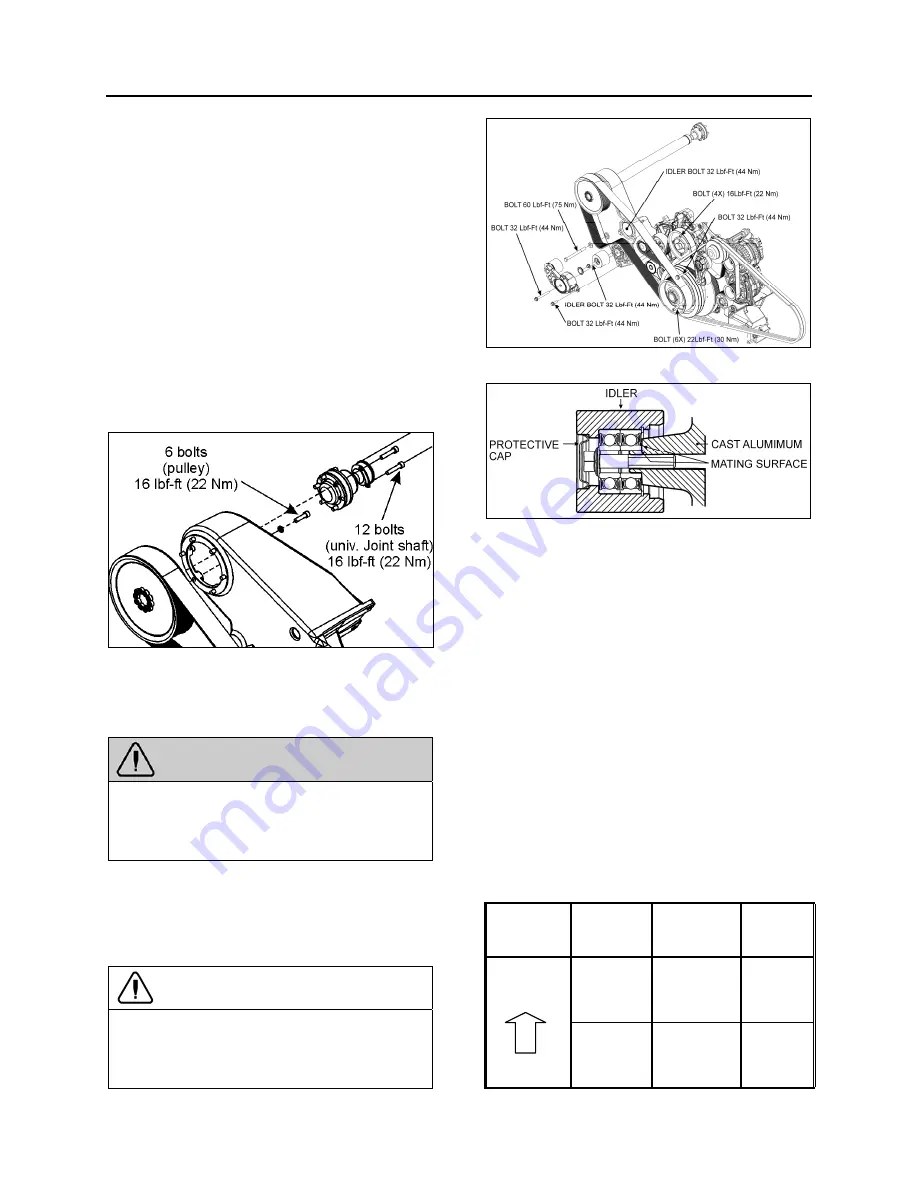
2. Dismount the drive pulley. Gain access to the
6 mounting bolts from behind the pulley,
through the opening in the cast aluminum
support (Fig. 23).
3. Unscrew and remove the universal joint shaft
mounting bolts (6) at the right angle gearbox.
4. Slowly, move the shaft toward the rear of the
vehicle.
5. Finally, dismount the universal joint shaft
from the drive pulley (6 bolts).
Installation of the universal joint shaft is the
same as removal, but in reverse order.
FIGURE 23: TIGHTENING SPECIFICATION
05123A
12.2 IDLER REPLACEMENT
If an idler is defective, replace as follow:
WARNING
Turn the ignition switch to the OFF position
and set starter selector switch to the OFF
position to prevent accidental starting of the
engine.
1. Remove the protective cap (replace with a
new one).
2. Unscrew the idler mounting bolt.
3. Replace idler with a new one.
CAUTION
When installing the idler, make sure it rests
perfectly against the bearing surface on the
cast aluminum support. If not, the drive belt
may slip of the idler. See following figure.
FIGURE 24: TIGHTENING SPECIFICATION (VOLVO D13
ENGINE)
FIGURE 25: IDLER MOUNTED ON THE CAST ALUMINUM
SUPPORT
4. Bolt the new idler on the cast aluminum
support. Tighten to 32 lbf-ft (44 Nm).
5. Place a new protective cap.
13. VARIABLE SPEED COOLING FAN
The cooling fan clutch has two thermostatically
controlled speeds, plus a neutral (clutch
disengaged). The engine control module
controls the speed by comparing data from
engine coolant temperature, charge air
temperature, Allison transmission oil
temperature (if applicable) and small A/C High
side pressure to a set of calibration data. The
fan drive clutch is electromagnetic; the engine
control module sends an electric current to
regulate speed by activating one magnetic coil
for the first speed and two magnetic coils for the
second speed.
The settings are:
Engine
coolant
temp.
Air intake
temp.
Allison
trans. oil
temp.
temperature
rising
208°F: fan
engages in
HIGH
SPEED
194°F: fan
engages in
HIGH
SPEED
230°F: fan
engages
in HIGH
SPEED
203°F: fan
engages in
LOW
SPEED
176°F: fan
engages in
LOW SPEED
216°F: fan
engages
in LOW
SPEED
Summary of Contents for X3-45 2016
Page 4: ......
Page 16: ...Section 00 GENERAL INFORMATION PA1593 12 FIGURE 12 METRIC US STANDARD CONVERSION TABLE 00005...
Page 17: ...Section 00 GENERAL INFORMATION 13 PA1593 FIGURE 13 CONVERSION CHART 00006...
Page 18: ......
Page 26: ......
Page 58: ......
Page 72: ...Section 04 EXHAUST AND AFTERTREATMENT SYSTEM PA1593 14 7 TORQUE SPECIFICATIONS...
Page 73: ...SECTION 04 EXHAUST AND AFTERTREATMENT SYSTEM PA1593 15...
Page 74: ...Section 04 EXHAUST AND AFTERTREATMENT SYSTEM PA1593 16...
Page 76: ......
Page 96: ......
Page 134: ......
Page 176: ...SECTION 06B ELECTRICAL 38 overcurrent working Circuit 306 shorted to ground...
Page 180: ......
Page 202: ......
Page 205: ...Section 09 PROPELLER SHAFT PA1593 3 FIGURE 1 PROPELLER SHAFT ASSEMBLY 09002...
Page 256: ......
Page 268: ......
Page 295: ...SECTION 16 SUSPENSION PA1593 9 2 5 TORQUE SPECIFICATIONS...
Page 296: ...Section 16 SUSPENSION PA1593 10...
Page 297: ...Section 16 SUSPENSION PA1593 11...
Page 314: ......
Page 380: ......
Page 388: ......
Page 413: ...Section 22 HEATING AND AIR CONDITIONING PA1593 15 FIGURE 18 REFRIGERANT CIRCUIT CENTRAL SYSTEM...
Page 433: ...Section 22 HEATING AND AIR CONDITIONING PA1593 35 FIGURE 36 CENTRAL HEATING SYSTEM COMPONENTS...


