Other Features
PA1627 X3-45 Operator’s Manual
5-40
Test Aim of Acoustic Sensor Beam
1. Move wheelchair and passenger slowly
towards doorway. TWS should detect
wheelchair and passenger (LED will flash,
buzzer will sound and the module red light
will flash) when centerline of front wheels is
between 18 and 24 inches from doorway.
2. Open vehicle access door above lift. Lower
platform to ground and place wheelchair and
passenger at rear of platform. Bridgeplate
should be up. Raise platform to floor level.
This normal platform motion with wheelchair
and passenger aboard should not actuate
TWS. If LED does flash (buzzer will also
sound and module red light will flash), turn
sensor adjustment screw slightly
counterclockwise.
NOTE
If an adjustment is made, repeat the previous
step where wheelchair is between 18 and 24
inches from doorway.
Adjust acoustic sensor timing
1. Support a flat sheet of cardboard or similar
material, directly beneath TWS module at a
distance of 4½ feet below module. Sheet
must be facing sensors.
NOTE
Before proceeding, visually inspect sensors to
verify that they are pointing directly at floor, or
nearly, and are not pointing off at an extreme
angle.
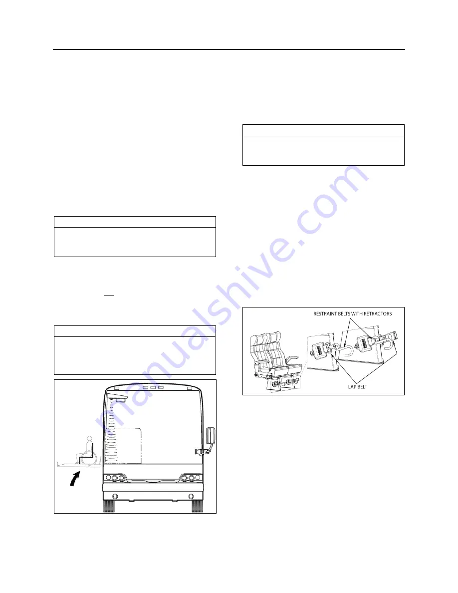
CHECKING NORMAL PLATFORM POSITION
23372
2. Note the sensor timing access hole. This
hole provides access to a plunger-actuated
switch that sets the sensor timing. Insert a
1/16-inch diameter wire-like object into the
access hole and press the plunger inward.
The LED will flash momentarily while the
module establishes the distance and then
remain on steady. Release the plunger
when the LED ceases to flash.
NOTE
It is important that objects, such as your body,
tools, seats, etc., do not interfere with the
beam while the adjustment is being made.
WHEELCHAIR RESTRAINT SYSTEMS
4-POINT SECUREMENT WITH ANCHORAGE
TO PASSENGERS SEAT PEDESTALS
This securement system includes:
Two (2) sets of four (4) wheelchair restraint
belts and retractors with anchorage to
passengers seat pedestals.
Occupant securements: lap and shoulder
belt.
WHEELCHAIR AND OCCUPANT RESTRAINT SYSTEM
To secure the wheelchair, four restraint belts
must be used (at all four corners). Hook one
wheelchair restraint belt to each corner of the
wheelchair frame
(not the wheels)
and allow
the retractors to tension the belts.
To remove the restraint belts, push down on the
tension release lever found on the retractor.
Unhook the wheelchair and allow the belts to
retract. Guide the belts in, making sure they
remain untwisted as they retract.
Summary of Contents for X3-45 2017
Page 1: ...OPERATOR S MANUAL X3 45 COACH...
Page 2: ......
Page 3: ...COACH MANUFACTURER OPERATOR S MANUAL X3 45 COACH Model Year 2018 PA1627 September 2017...
Page 8: ......
Page 12: ......
Page 28: ...Coach Exterior PA1627 X3 45 Operator s Manual 2 16...
Page 42: ...Coach Interior PA1627 X3 45 Operator s Manual 3 14...
Page 100: ...Controls and Instruments PA1627 X3 45 Operator s Manual 4 58...
Page 186: ...Care and Maintenance PA1627 X3 45 Operator s Manual 8 22...
Page 200: ...Technical Information PA1627 X3 45 Operator s Manual 9 14...
Page 202: ......


