IN-STATION LIGHTING
The in-station lighting system circuit is linked
with the optional battery charger: When the
charger is connected to an external power
source, the in-station lighting circuit can be
energized without depleting the batteries.
The receptacle used for the battery charger is
located on the main power compartment door.
ENGINE COOLANT HEATER
This optional auxiliary heating system is used for
preheating and retaining the heat of water-
cooled engines. It can be used before startup to
ease starting and to provide rapid operation of
the interior heating system. It can also be used
with the engine running to maintain coolant heat
and interior temperature.
The heater operates independently of the
engine. It is connected to the cooling system,
heating circuits and to the vehicle’s fuel and
electrical system.
SWITCHING THE HEATER ON
The timer light illuminates when the heater is
switched
ON
. Air is forced in to flush out the
combustion chamber of residual gases and the
water circulation pump begins operating. The
fuel metering pump delivers fuel in precise
amounts to the combustion chamber, where fuel
and combustion air form a combustible mixture
which is ignited by the ignition unit.
Once the flame sensor has signaled to the
control unit that combustion has taken place, the
ignition unit is switched
OFF.
The dashboard
telltale light will illuminate to indicate when the
burner is
ON.
Hot combustion gases are diverted at the end of
the flame pipe and are then forced through the
indirect heating surfaces of the heat exchanger.
The heat exchanger transfers the heat to the
Other Features 5-27
coolant water passing through the heat
exchanger.
!
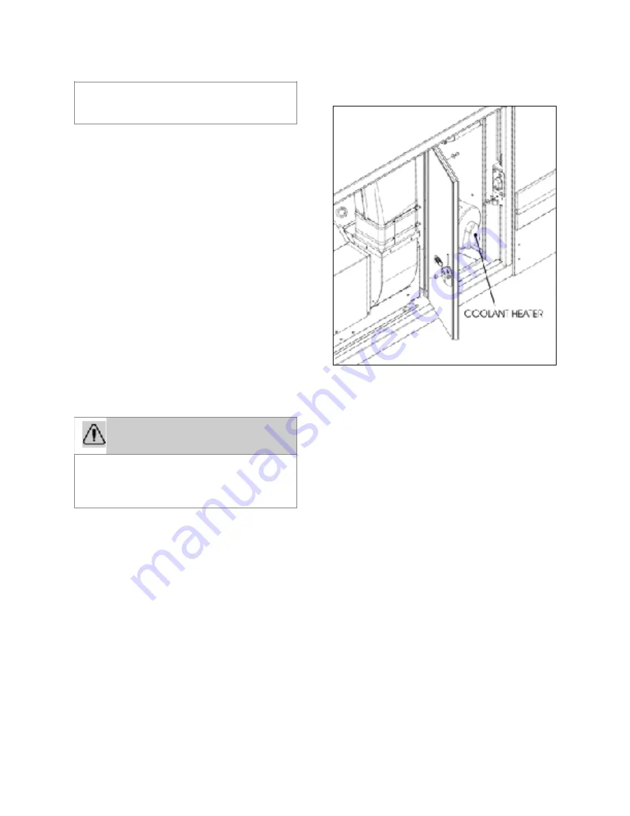
LOCATION OF PREHEATER
18607
The heater is thermostatically controlled and
operates intermittently (i.e., the switched-on time
of the burner varies depending on the heat
requirement). The water temperature is
controlled by the built-in water thermostat.
The water circulation pump remains in operation
as long as the heater is operating, even during
the regulated intervals and during the delayed
cut-out of the heater. The pump can also be
operated independently of the heater by means
of an appropriate circuit. The heater can be
switched
ON
at any time (i.e., during the delayed
cut-out period). Ignition takes place after the
delayed cut-out time expires.
SWITCHING THE HEATER OFF
The fuel supply is interrupted when the heater is
switched
OFF
. This causes the flame to go out
and a delayed cut-out of 2.5 minutes begins. The
circulating combustion air flushes the remaining
combustion gases out of the chamber and cools
off the heated parts on the exhaust side of the
heat exchanger. The water circulation pump
continues to transfer the latent heat present in
the heat exchanger, thus preventing hot spots.
Once the delayed cut-out time expires, both the
combustion air blower and the water circulation
pump switch
OFF
automatically. A cut-out will
automatically take place in case of heater failure.
In order to prevent damage to the
suspension, always raise the tag axle before
lifting the coach.
WARNING
The coolant heating system uses the same
fuel as the engine. Do not operate in a
closed building or while refueling. Operate
only in a well ventilated area.
!
Summary of Contents for X3-45 COACH
Page 1: ...OPERATOR S MANUAL X3 45 COACH ...
Page 2: ......
Page 3: ...COACH MANUFACTURER OPERATOR S MANUAL X3 45 COACH PA1609 December 2015 ...
Page 8: ......
Page 13: ......
Page 18: ... WARNING Unless otherwise stated do not run the engine when the engine compartment is open ...
Page 25: ...either open or shut A key is provided for unlocking the door if the option was chosen ...
Page 153: ... ...
Page 164: ......
Page 176: ......
Page 189: ...INTERIOR UNLATCH AIR VALVE 12164 ...
Page 190: ...7 4 Safety Features and Equipment UNLATCH AIR VALVE LOCATION 12209 ...
Page 192: ...an audible alarm will sound 2 The operator shall bring the vehicle to a safe stop ...
Page 213: ......
Page 220: ......
Page 239: ...9 2 Technical Information VEHICLE IDENTIFICATION NUMBER VIN 13 COACH FINAL RECORD 13 ...
Page 240: ...Technical Information 9 3 X3 45 OVERALL DIMENSIONS SIDE ELEVATION 18673_1 ...
Page 241: ...9 4 Technical Information X3 45 OVERALL DIMENSIONS TOP FRONT AND REAR VIEWS 18674_1 ...
Page 256: ......
Page 258: ......
Page 262: ......
Page 264: ...4 Try disconnecting the CECM ...
Page 266: ......
Page 268: ......
Page 292: ......


