5-36 OTHER FEATURES
PA1633 X3-45 Commuter Operator’s Manual
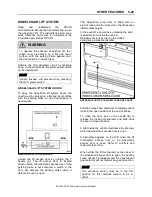
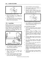
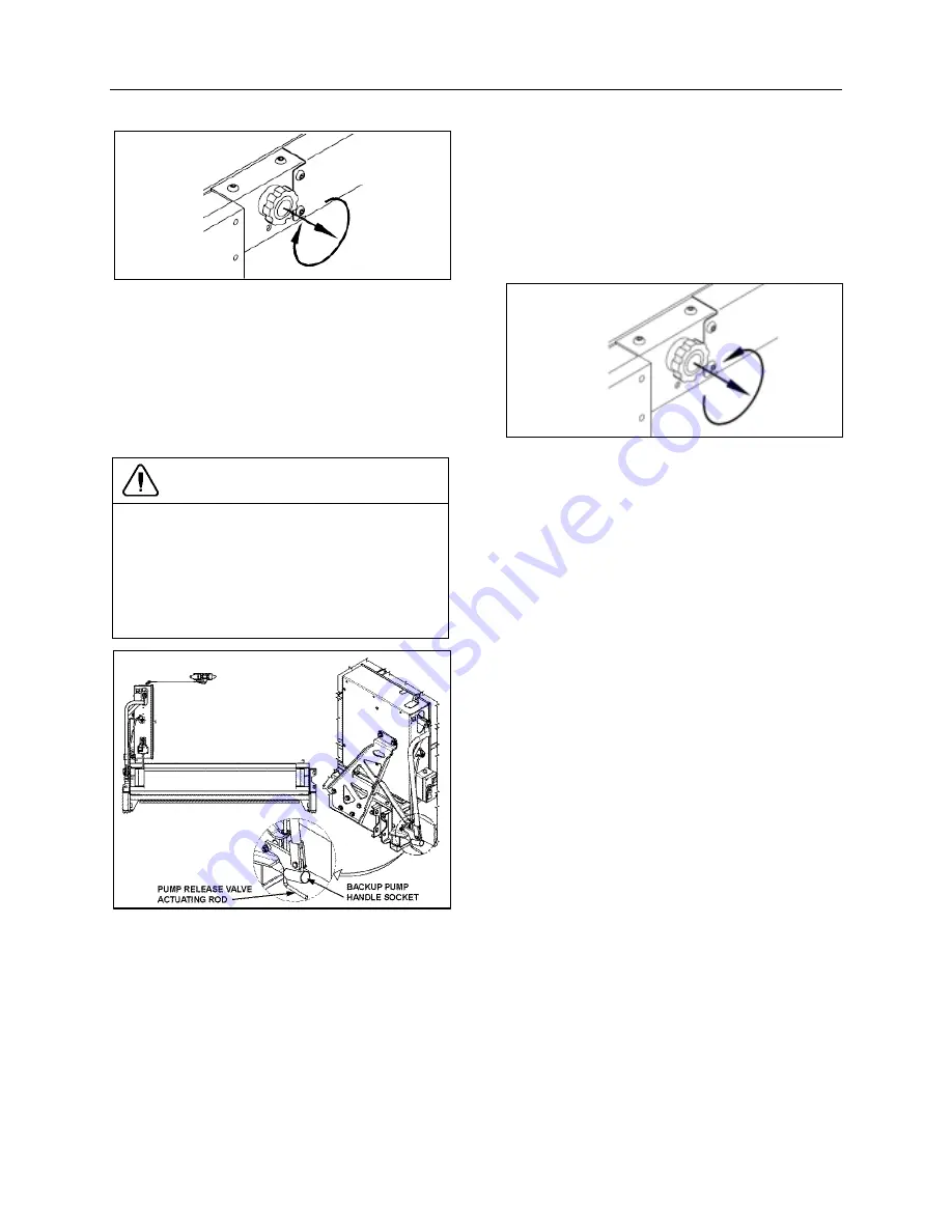
CLOCKWISE ROTATION CLOSES ROLLSTOP
23275
3. Verify that rollstop is up (closed). Pull
rollstop control knob out and rotate fully
clockwise, if it isn’t up.
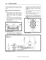
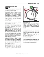
4. Insert handle extension into manual backup
pump handle socket and pump to raise the
platform to the vehicle floor level.
CAUTION
During manual rising of the lift, do not raise
the platform more than 1-1/2 inches above the
vehicle floor level. Any excessive travel will
make it difficult to enter the platform and/or
damage the lift bridge plate actuator. The
outer edge of the bridge plate must rest
squarely on the vehicle floor.
WHEELCHAIR LIFT MANUAL HYDRAULIC PUMP
23373
5. The lift passenger and attendant must follow
the instructions to ENTER or EXIT the
vehicle, as previously described.
To manually lower the platform
1. Verify that rollstop is up (closed). Pull
rollstop control knob out and rotate
clockwise, if it isn’t up.
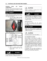
2. Slowly pull the pump release valve actuating
rod UP until the platform begins to lower
(opening the release valve lowers platform).
3. Allow the platform to reach ground level.
4. Push the pump release valve actuating rod
back DOWN until lightly-snug.
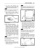
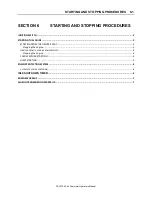
5. Using the rollstop manual control knob,
OPEN the rollstop. Pull rollstop control knob
out and rotate fully counterclockwise.
Rollstop must lie flat on ground.
COUNTERCLOCKWISE ROTATION OPENS ROLLSTOP
6. The attendant and lift passenger should
follow the instructions to ENTER or EXIT the
vehicle, as described previously.
To manually stow the platform
1. Detach the restraint belt, lift each handrail
up to unlock and fold handrails. Re-fasten
restraint belt.
2. Raise or lower the platform to the
deploy/stow position; the platform frame
must be parallel to the side of the lift
enclosure. If the exact position cannot be
obtained, slightly low is preferred to slightly
high.
3. Using the rollstop manual control knob and
one hand one the rollstop, close the rollstop
until it latches.
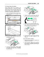
4. Turn the manual platform release shafts
using pump handle extension to disengage
the platform.
5. Use one person on each side of the lift to
prevent mechanical binding.
6. With fingers up and palms forward, push the
platform forcefully to start the lift moving
inward. As the lift begins to move inward,
maintain a constant pushing motion until the
lift comes to rest completely inside the lift
enclosure.
7. Push firmly and make sure that the platform
manual release shafts have turned to lock
the platform.
Summary of Contents for X3-45 COMMUTER 2018
Page 1: ...OPERATOR S MANUAL X3 45 COMMUTER COACH...
Page 2: ......
Page 3: ...COACH MANUFACTURER X3 45 COMMUTER OPERATING MANUAL March 2018...
Page 4: ...PA1633 MARCH 2018 Featuring REVISION DESCRIPTION DATE FIRST RELEASE 03 2018...
Page 8: ......
Page 12: ......
Page 70: ...4 36 CONTROLS AND INSTRUMENTS PA1633 X3 45 Commuter Operator s Manual...
Page 108: ...5 38 OTHER FEATURES PA1633 X3 45 Commuter Operator s Manual...
Page 116: ...6 8 STARTING AND STOPPING PROCEDURES PA1633 X3 45 Commuter Operator s Manual...
Page 120: ...7 4 SAFETY FEATURES AND EQUIPMENT PA1633 X3 45 Commuter Operator s Manual KIDDE IMAGES...
Page 128: ...7 12 SAFETY FEATURES AND EQUIPMENT PA1633 X3 45 Commuter Operator s Manual...
Page 148: ...8 20 CARE AND MAINTENANCE PA1633 X3 45 Commuter Operator s Manual...
Page 150: ...9 2 TECHNICAL INFORMATION PA1633 X3 45 Commuter Operator s Manual OVERALL DIMENSIONS...
Page 158: ...9 10 TECHNICAL INFORMATION PA1633 X3 45 Commuter Operator s Manual...
Page 160: ......
Page 164: ......

