6-2 STARTING AND STOPPING PROCEDURES
PA1633 X3-45 Commuter Operator’s Manual
IGNITION SWITCH
Vehicles are equipped with an ignition lever
instead of an ignition key. Use the ignition lever
to activate the electrical circuit by turning it to the
ON position.
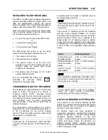
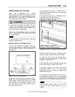
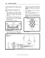
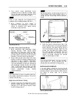
IGNITION SWITCH POSITIONS
06354
CAUTION
When the vehicle is parked overnight or for an
extended period of time, the ignition switch
should be set to the OFF position.
NOTE
When the battery master switch is set to the
OFF position, all electrical supply from the
batteries is cut off, with the exception of
battery equalizer check module, ECM ignition
and power supply, Allison TCM power,
entrance door and fire alarm.
The ignition switch doubles as the battery
master switch. Any position other than OFF
activates the electrical circuits. Electrical circuits
are also activated when the hazard switch is
depressed. Two auxiliary master switches in
series with the ignition switch are installed on
the vehicle; one is located on the rear electrical
panel and one in the engine compartment on the
rear start panel, for maintenance ease.
The ignition switch is located on the lower left
side of the dashboard. It has three positions:
Off
- In the OFF position, ignition cannot take
place.
The electrical circuits are not activated when the
switch is in this position. Only the accessories
connected directly to the batteries can be
activated. Maintain the switch in this position
when parked overnight or for an extended
period.
On
- Turn the lever clockwise to the first position
to place the ignition switch to ON. Do not leave
the lever in this position unless the engine is
running.
Start –
Use this position to crank the engine.
The ignition switch is equipped with a starter
protection which inhibits turning the lever to the
START position if the lever has not previously
been turned to the OFF position.
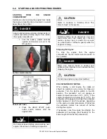
STARTING THE ENGINE
In normal circumstances, the engine should be
started from the driver’s seat. However, a rear-
start panel in the engine compartment permits
starting the engine from that location, mainly for
maintenance purposes.
STARTING FROM THE DRIVER’S SEAT
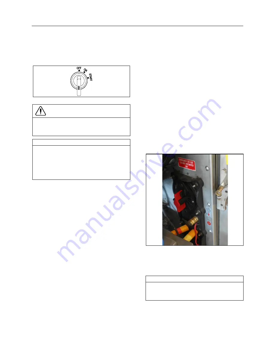
1. Make sure the rear start selector
switch located in the engine
compartment is set to the NORMAL
position and that the battery master
switch (master cut-out) located on
the rear electrical panel is set to the
ON position.
BATTERY MASTER SWITCH 06850
2. Make sure the parking brake is
applied, if not, apply the parking
brake by pulling the parking brake
control button all the way up.
NOTE
An electronic protection will prevent the engine
from starting if the parking brake is not
applied.
3. Turn ignition switch to ON and wait
a few second;
Summary of Contents for X3-45 COMMUTER 2018
Page 1: ...OPERATOR S MANUAL X3 45 COMMUTER COACH...
Page 2: ......
Page 3: ...COACH MANUFACTURER X3 45 COMMUTER OPERATING MANUAL March 2018...
Page 4: ...PA1633 MARCH 2018 Featuring REVISION DESCRIPTION DATE FIRST RELEASE 03 2018...
Page 8: ......
Page 12: ......
Page 70: ...4 36 CONTROLS AND INSTRUMENTS PA1633 X3 45 Commuter Operator s Manual...
Page 108: ...5 38 OTHER FEATURES PA1633 X3 45 Commuter Operator s Manual...
Page 116: ...6 8 STARTING AND STOPPING PROCEDURES PA1633 X3 45 Commuter Operator s Manual...
Page 120: ...7 4 SAFETY FEATURES AND EQUIPMENT PA1633 X3 45 Commuter Operator s Manual KIDDE IMAGES...
Page 128: ...7 12 SAFETY FEATURES AND EQUIPMENT PA1633 X3 45 Commuter Operator s Manual...
Page 148: ...8 20 CARE AND MAINTENANCE PA1633 X3 45 Commuter Operator s Manual...
Page 150: ...9 2 TECHNICAL INFORMATION PA1633 X3 45 Commuter Operator s Manual OVERALL DIMENSIONS...
Page 158: ...9 10 TECHNICAL INFORMATION PA1633 X3 45 Commuter Operator s Manual...
Page 160: ......
Page 164: ......


