TECHNICAL INFORMATION 9-7
PA1633 X3-45 Commuter Operator’s Manual
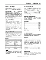
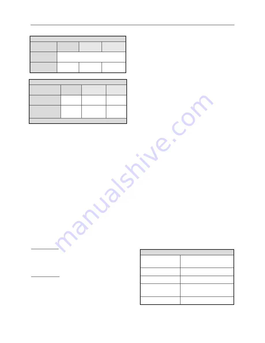
DRIVE AXLE ZF A-132
Minimum
value
Nominal
value
Maximum
value
Thrust
angle
±0.11°
Total toe
0.15°
toe-in
0°
0.15°
toe-out
TAG AXLE
Minimum
value
Nominal
value
Maximu
m value
Thrust angle*
(degrees)
-0.02
0
0.02
Total toe
0.08°
toe-in
0°
0.02°
toe-out
(*) Use the drive axle as reference
COOLING SYSTEM
•
Extra capacity, copper fin radiator and
aluminum charge air cooler arranged one
behind the other.
•
3 speed fan clutch engine ECM controlled.
•
Rubber insulated from the body.
•
Expansion tank above radiator and remote
mounted.
•
System pressure 13 psi.
•
185
o
F thermostat.
•
System capacity 24 us gal.
•
Coolant filter.
•
Radiator fan: 38 inches fan belt and drive
shaft driven.
FUEL SYSTEM
Steel fuel tank
Fuel legal capacity (corresponding to 95% of
gross capacity): 180 US gallons (681 liters).
Unusable fuel: 6.3 US gallons (24 liters).
Equipped with:
•
Emco Wheaton fuel filling system.
•
Provided with filling access on the right side
of the coach with safety filler cap.
•
Pressure relief valve.
•
Electric fuel gauge.
•
Low level signal at 26 US gallons/98.4 liters.
•
Primary filter 25 microns (standard).
•
Fuel pro 382 filter as primary filter.
•
Secondary filter 3 to 5 microns.
•
Shut-off valve on fuel supply line.
EXHAUST SYSTEM
One all stainless steel exhaust aftertreatment
system including:
•
Catalylic converter to reduce NOx.
•
FleetGuard assembly made of a DOC (Diesel
Oxidation Catalyst and a DPF (Diesel
Particulate Filter). Noise, vibration and heat
insulated. This assembly is mounted to the
bus structure and is accessible through an
exterior access door.
•
Tail pipe diffuser and rain deviation device.
•
Exhaust pipe with insulation and a flexible
section.
•
Exhaust to rear left hand top of rear cap.
•
Diesel exhaust fluid (DEF) tank (15.9 gal.)
and injection system.
HEATING AND AIR CONDITIONING
The large capacity A/C provides adequate
capacity of conditioned and filtered air for all
climatic conditions. Fresh air is drawn into the
system from the left (driver’s) side of the vehicle.
Return air is taken from the middle of the
vehicle. The driver’s heater and defogger are
controlled separately from the central unit. An
air mixture selector enables air to be drawn into
the system from outside the vehicle or
recirculated.
CENTRAL A/C
Air conditioning
capacity
9 tons
Refrigerant type
134A
Heating capacity
152 000 Btu/h
Air flow, overhead
parcel rack evap.
450 cfm (12,7 m
3
/min)
Air flow, main A/C
2 600 cfm (73,6 m
3
/min)
Summary of Contents for X3-45 COMMUTER 2018
Page 1: ...OPERATOR S MANUAL X3 45 COMMUTER COACH...
Page 2: ......
Page 3: ...COACH MANUFACTURER X3 45 COMMUTER OPERATING MANUAL March 2018...
Page 4: ...PA1633 MARCH 2018 Featuring REVISION DESCRIPTION DATE FIRST RELEASE 03 2018...
Page 8: ......
Page 12: ......
Page 70: ...4 36 CONTROLS AND INSTRUMENTS PA1633 X3 45 Commuter Operator s Manual...
Page 108: ...5 38 OTHER FEATURES PA1633 X3 45 Commuter Operator s Manual...
Page 116: ...6 8 STARTING AND STOPPING PROCEDURES PA1633 X3 45 Commuter Operator s Manual...
Page 120: ...7 4 SAFETY FEATURES AND EQUIPMENT PA1633 X3 45 Commuter Operator s Manual KIDDE IMAGES...
Page 128: ...7 12 SAFETY FEATURES AND EQUIPMENT PA1633 X3 45 Commuter Operator s Manual...
Page 148: ...8 20 CARE AND MAINTENANCE PA1633 X3 45 Commuter Operator s Manual...
Page 150: ...9 2 TECHNICAL INFORMATION PA1633 X3 45 Commuter Operator s Manual OVERALL DIMENSIONS...
Page 158: ...9 10 TECHNICAL INFORMATION PA1633 X3 45 Commuter Operator s Manual...
Page 160: ......
Page 164: ......


