CONTROLS AND INSTRUMENTS 4-25
PA1633 X3-45 Commuter Operator’s Manual
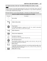
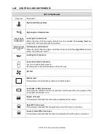
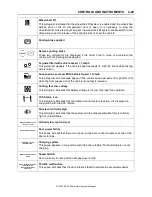
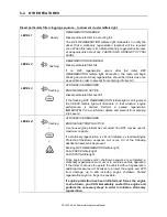
STOP, CHECK AND INFORMATION
TELLTALE LIGHTS
STOP and CHECK telltale lights illuminate
automatically to draw the attention of the driver
and their associated messages are displayed in
the DID. More than one message (see
“Acknowledging Messages” below) can be
active at the same time. A displayed message
can be replaced by a new message provided the
new message has a higher priority. Only fault
codes that have a direct impact on vehicle
operation are displayed. All fault codes are
stored in the appropriate ECU for access by
service technicians.
STOP Telltale Light
In the event of a serious fault, the red STOP
telltale light comes on and an audible alarm will
sound if the engine is running. An illuminated
stop message light indicates a serious problem
has been detected, and the driver must respond
immediately to the problem.
When illuminating, this telltale light means the
vehicle must be safely pulled off the road and
stopped. In some instances, the engine must be
switched off immediately.
WARNING
Failure to stop and take necessary action
when the stop telltale light is on can result in
automatic engine derate and shutdown.
In some cases preventive action may be taken
by the engine ECU to protect the engine. For
further details, refer to “Engine Protection
System” in STARTING AND STOPPING
PROCEDURES section.
CHECK Telltale Light
This telltale light means that a fault or an
abnormal operating condition has been
detected. The vehicle must be checked at the
next stop.
If the CHECK telltale light illuminates, an
associated message is displayed in the DID.
Always pay attention to the associated
messages (see “Acknowledging Messages”
below).
ACKNOWLEDGING MESSAGES
A fault message associated to a STOP or
CHECK telltale light must be acknowledged by
pressing the ESCAPE or ENTER button after
which the display returns to the same status that
existed before the fault occurred. All messages
can be acknowledged. Acknowledged but
inactive messages are displayed again when the
ignition key is turned to the START position or
they can be read in the DID menu. Refer to
OTHER FEATURES for more information on the
DID menus.
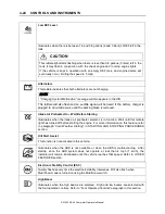
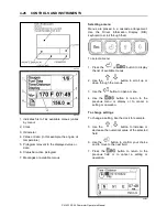
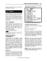
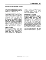
DRIVER INFORMATION DISPLAY
The DID (Driver Information Display) is located
in the center of the instrument cluster. It displays
digital gauges, main menus and sub-menus that
provide necessary and important information to
the driver. The information available to the driver
depends on vehicle configuration, and whether
the vehicle is in operation or parked. For the list
of the available menus and sub-menus, refer to
“Driver Information Display Menus” in OTHER
FEATURES section.
06746
The outside air temperature, fuel flow and the
odometer (Allison transmission) are part of the
default display. You can replace the default
display by your selection of favorite gauges
using the Driver Information Display sub-menu
Favorite Display Setting. Refer to
Other
Features
section for more information.
Summary of Contents for X3-45 COMMUTER 2018
Page 1: ...OPERATOR S MANUAL X3 45 COMMUTER COACH...
Page 2: ......
Page 3: ...COACH MANUFACTURER X3 45 COMMUTER OPERATING MANUAL March 2018...
Page 4: ...PA1633 MARCH 2018 Featuring REVISION DESCRIPTION DATE FIRST RELEASE 03 2018...
Page 8: ......
Page 12: ......
Page 70: ...4 36 CONTROLS AND INSTRUMENTS PA1633 X3 45 Commuter Operator s Manual...
Page 108: ...5 38 OTHER FEATURES PA1633 X3 45 Commuter Operator s Manual...
Page 116: ...6 8 STARTING AND STOPPING PROCEDURES PA1633 X3 45 Commuter Operator s Manual...
Page 120: ...7 4 SAFETY FEATURES AND EQUIPMENT PA1633 X3 45 Commuter Operator s Manual KIDDE IMAGES...
Page 128: ...7 12 SAFETY FEATURES AND EQUIPMENT PA1633 X3 45 Commuter Operator s Manual...
Page 148: ...8 20 CARE AND MAINTENANCE PA1633 X3 45 Commuter Operator s Manual...
Page 150: ...9 2 TECHNICAL INFORMATION PA1633 X3 45 Commuter Operator s Manual OVERALL DIMENSIONS...
Page 158: ...9 10 TECHNICAL INFORMATION PA1633 X3 45 Commuter Operator s Manual...
Page 160: ......
Page 164: ......

