OTHER FEATURES 5-27
PA1633 X3-45 Commuter Operator’s Manual
INTELLIGENT SLEEP MODE (ISM)
The ISM is a battery-saving feature designed to
monitor the battery State Of Charge (SOC). The
ISM will automatically change the vehicle
electrical system from normal functional state to
sleep mode if the battery SOC falls below 65%.
Once the vehicle has entered into sleep mode,
the only actions needed to put the vehicle back
into its normal functional state are:
•
To cycle the ignition lever from OFF to ON;
or
•
To open the entrance door;
or
•
To turn on the hazard lights.
The ISM forces the vehicle to go into sleep
mode if all the following conditions are met:
1. The engine is not running;
2. The parking brake is applied
3. The ignition switch is at the ON, ACC
positions or at the OFF position but the 15
minutes “wake up” period after engine
shutdown is not expired.
4. The battery state of charge of 12V or 24V
system falls below 65%.
The red ALTERNATOR telltale will
illuminate 30 seconds before
activation of the sleep mode.
TRANSMISSION OUTPUT RETARDER
The transmission output retarder is a device that
helps to reduce the speed of a vehicle. It
improves vehicle control, increases driving
safety and permits more economical operation.
The retarder provides slowing power when it is
most needed, such as when descending
mountain roads, in stop-and-go traffic and on
crowded freeways.
The transmission output retarder is a vehicle-
slowing device, not a vehicle-stopping device. It
is not a substitute for the service braking
system. The service brake must be used to bring
the vehicle to a complete stop.
NOTE
Extended use of transmission output retarder
will raise the temperature of the transmission
fluid.
A disable switch is located in the RJB close to
the master brake interlock.
NOTE
Deactivating the transmission retarder will turn
the indicator light located at the front of the
coach ON.
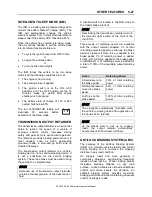
Three levels of retarding power are available
with the output retarder enabled: 1/3 of total
retarding power is applied as soon as the brake
pedal is pressed. If more force is applied to the
brake pedal, 1/3 of retarding power is added.
Finally, with full force applied to the brake pedal,
an additional 1/3 of retarding power is added for
a total of 100% of the available output retarding
power.
Action
Retarding Power
Initial pressure on
the brake pedal
33% of total retarding
power
Additional pressure
on service brake
pedal
66% of total retarding
power
Full force on the
brake pedal
100% of total retarding
power
NOTE
The stoplights automatically illuminate when
the vehicle is slowing down after application of
the transmission retarder.
NOTE
As the wheels start to lock up on slippery
roads, the output retarder automatically
deactivates until the wheels roll freely.
ANTILOCK BRAKING SYSTEM
(ABS)
The purpose of the Antilock Braking System
(ABS) is to maintain vehicle stability and control
during braking and to minimize the stopping
distance in any road condition.
On slippery roads and more generally in
emergency situations, over-braking frequently
induces wheel locking. Wheel locking greatly
increases breaking distance on any road
surface. Locked wheels also impede directional
control and cause severe tire abrasion. An
antilock braking system provides maximum
braking performance while maintaining adequate
control on slippery roads.
Summary of Contents for X3-45 COMMUTER 2018
Page 1: ...OPERATOR S MANUAL X3 45 COMMUTER COACH...
Page 2: ......
Page 3: ...COACH MANUFACTURER X3 45 COMMUTER OPERATING MANUAL March 2018...
Page 4: ...PA1633 MARCH 2018 Featuring REVISION DESCRIPTION DATE FIRST RELEASE 03 2018...
Page 8: ......
Page 12: ......
Page 70: ...4 36 CONTROLS AND INSTRUMENTS PA1633 X3 45 Commuter Operator s Manual...
Page 108: ...5 38 OTHER FEATURES PA1633 X3 45 Commuter Operator s Manual...
Page 116: ...6 8 STARTING AND STOPPING PROCEDURES PA1633 X3 45 Commuter Operator s Manual...
Page 120: ...7 4 SAFETY FEATURES AND EQUIPMENT PA1633 X3 45 Commuter Operator s Manual KIDDE IMAGES...
Page 128: ...7 12 SAFETY FEATURES AND EQUIPMENT PA1633 X3 45 Commuter Operator s Manual...
Page 148: ...8 20 CARE AND MAINTENANCE PA1633 X3 45 Commuter Operator s Manual...
Page 150: ...9 2 TECHNICAL INFORMATION PA1633 X3 45 Commuter Operator s Manual OVERALL DIMENSIONS...
Page 158: ...9 10 TECHNICAL INFORMATION PA1633 X3 45 Commuter Operator s Manual...
Page 160: ......
Page 164: ......


