SAFETY FEATURES AND EQUIPMENT 7-5
PA1633 X3-45 Commuter Operator’s Manual
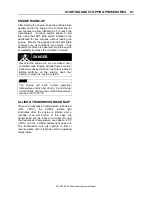
Starting the Vehicle after Triggering Of a Fire
Alarm
The vehicle may be started after a fire alarm
without resetting the system. Refer to ignition
switch sequence below. This will not reset the
system; rather it will instruct the vehicle’s
multiplex system to ignore vehicle interface
outputs from the protection panel. This feature is
intended to be used only in emergency
situations that require the vehicle to be restarted
and moved a short distance prior to system
reset. It should not be performed if the cause of
the fire alarm has not been clearly identified and
corrected.
To start the vehicle, perform this ignition switch
sequence within 2 seconds:
1.
From the on position, turn to
OFF
2.
Return to ON and START.
TIRE PRESSURE MONITORING SYSTEM
(TPMS)
The coach is equipped with a Tire Pressure
Monitoring System (TPMS). The system
monitors tire temperature and pressure.
If pressure and/or temperature exceed a certain
value for a set number of seconds, a warning
buzzer will be heard and a message will appear
in the DID. The following paragraphs describe
four different situations it might occur.
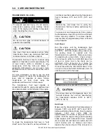
1) CRITICALLY LOW PRESSURE WARNING
A critically low pressure
warning will trigger if a tire
pressure falls below 45 psi.
An audible warning sound
will be heard and the check pictogram remains
illuminated.
2) HIGH TEMPERATURE WARNING
High temperature warning
will trigger if a tire
temperature rise above
194°F/90°C. An audible
warning sound will be heard and the check
pictogram flashes.
3) HIGH TEMPERATURE ALARM
It indicates a critical alert. A
high temperature alert will
trigger if a tire temperature
rise above 212°F/100°C. An
audible warning sound will be heard and the
stop pictogram flashes. Stop the vehicle as soon
as possible.
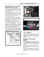
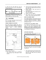
4) TPMS MALFUNCTION
In case of system
malfunction, the
following warning
popup message
will show on the DID to warn the driver that the
TPMS might be disabled or unreliable.
Description
System includes the following elements:
•
Special tire valves;
•
RF sensor inside each tire, fixed to the
valve;
•
3 antennas to receive the sensors RF signal
(one in the front spare tire compartment, one
above the L.H. side rear wheels and one
above the R.H. side rear wheels);
•
A TPMS receiver connected to the antennas
and located in the front electrical
compartment, above the CECM;
The section of the special tire valves located
inside the tire is dome-shaped to allow fixing the
sensor.
Sensors provide continuous tire pressure and
temperature reading.
The normal sensor battery lifespan is 5 years.
The remaining lifespan is displayed as a
percentage in the TPMS display.
NOTE
It is recommended to check the remaining
battery lifespan when changing the tires in
order to replace the sensors at the same time
if they are due for replacement before the next
change.
The screw fixing the sensor to the valve can only
be used once because the threads are powder-
coated to lock the sensor in place and prevent
unfastening.
Summary of Contents for X3-45 COMMUTER 2018
Page 1: ...OPERATOR S MANUAL X3 45 COMMUTER COACH...
Page 2: ......
Page 3: ...COACH MANUFACTURER X3 45 COMMUTER OPERATING MANUAL March 2018...
Page 4: ...PA1633 MARCH 2018 Featuring REVISION DESCRIPTION DATE FIRST RELEASE 03 2018...
Page 8: ......
Page 12: ......
Page 70: ...4 36 CONTROLS AND INSTRUMENTS PA1633 X3 45 Commuter Operator s Manual...
Page 108: ...5 38 OTHER FEATURES PA1633 X3 45 Commuter Operator s Manual...
Page 116: ...6 8 STARTING AND STOPPING PROCEDURES PA1633 X3 45 Commuter Operator s Manual...
Page 120: ...7 4 SAFETY FEATURES AND EQUIPMENT PA1633 X3 45 Commuter Operator s Manual KIDDE IMAGES...
Page 128: ...7 12 SAFETY FEATURES AND EQUIPMENT PA1633 X3 45 Commuter Operator s Manual...
Page 148: ...8 20 CARE AND MAINTENANCE PA1633 X3 45 Commuter Operator s Manual...
Page 150: ...9 2 TECHNICAL INFORMATION PA1633 X3 45 Commuter Operator s Manual OVERALL DIMENSIONS...
Page 158: ...9 10 TECHNICAL INFORMATION PA1633 X3 45 Commuter Operator s Manual...
Page 160: ......
Page 164: ......

