SECTION 06: ELECTRICAL
DOB 2490-2789 | X3-45 Commuter PA1605 Maintenance Manual (Final Version) – Sec 06 revised June 2017
29
The multiplex modules are connected by a
controller area network according to the layout
above.
A backup spare network is pre-wired in the
coach to quickly resolve any connectivity issue.
Spare connectors for this network are identified
by “s” e.g.:
c5s
is the spare for
c5
.
With the introduction of obd 2013 emissions
standard, we now have a high speed can
diagnostic and engine programming network,
also known as an iso network.
Refer to the list below for cross reference
between the current sae data line designation
and the former designation:
Dl-0 = prevost can 1 or
b-bus
Dl-1 =
j-1939
ecu communication, engine,
abs, allison
Dl-2 = can
iso
for engine diagnostics and
software download
Dl-3 = can 2 or
d- bus
Dl-4 =
j1587
drive train information network
Dl-5 & 6 = not used
Dl-7 = power train subnet or engine can
Dl-8 = not used (eaton)
Dl-9 = not used on this vehicle (i-shift to volvo
engine)
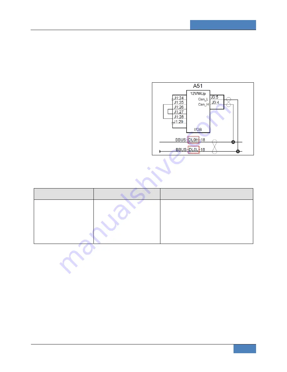
On wiring diagrams, the sae standard data link
designation appears. The different networks will
be identified on the data wire identification.
FIGURE 27: DATA WIRE IDENTIFICATION
4.8 MULTIPLEX
TROUBLESHOOTING
Problem/symptom
Probable causes
Actions
Vehicle does not start
Rear start selector switch is
not in the normal position
Master cut-out switch on the
rear electrical panel is in the
off position (down)
1. Check that the rear start selector
switch is flipped up to normal start
position and master cut-out switch is
flipped up to on and retry cranking
2. Flip the rear start selector switch to
“rear start” and start the vehicle from
the rear


