SECTION 07: TRANSMISSION
12
DOB 2490-2789 | X3-45 Commuter PA1605 Maintenance Manual (Final Version – Rev.2 April 2016)
Recommended torque is between 42-50 Lbf-
ft (57-68 Nm).
7. Remove the guide bolt through the access
opening in the flywheel housing. Replace it
with a self-locking screw, finger-tighten then
start the remaining screws; tighten to 17-21
lbf-ft (23-28 Nm). Place a wrench on the
crankshaft pulley attaching screw to turn the
converter to gain access to the threaded
holes.
NOTE
Remove the plug located below starter motor
and install cranking tool (88800014). Crank the
engine to gain access to the threaded holes by
turning the cranking tool using a suitable
adapter.
Reinstall starter motor and connect cables.
Reinstall access plug below starter motor.
8. Remove jack from under transmission.
9. Connect all sensors.
10. Connect the main wiring harness.
11. Connect the air supply line (steel-braided
hose) to the retarder control valve (if
applicable).
12. Connect the two transmission oil cooler
hoses as they were previously.
13. Reinstall clamps and brackets, and replace
locking ties previously removed during
removal procedure.
14. Install propeller shaft and its safety guard.
Refer to Section 09,
"PROPELLER SHAFT".
15. Install transmission dipstick and filler tube.
16. Install cross member under transmission.
17. Install engine splash guards.
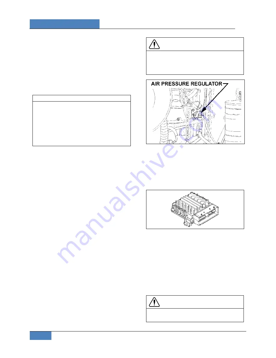
18. Adjust the retarder pressure to 80 ± 3 psi with
the air pressure regulator. For more
information refer to Section 12,
"BRAKE AND
AIR SYSTEM
", under heading
"AIR
PRESSURE REGULATOR".
The air pressure
regulator is located at back of engine
compartment, on R.H. side (Figure 8) or in
the R.H. side rear service compartment.
19. Make sure that the drain plug is in place, and
then remove the transmission dipstick and
pour approximately 24 US quarts (23 L) of
automatic transmission fluid through the filler
tube. Check and adjust oil level.
CAUTION
Do not overfill the transmission. Overfilling can
cause oil aeration (milky appearance) and
overheating. If overfilling occurs, drain oil as
required to bring it to the proper level.
FIGURE 8: AIR PRESSURE REGULATOR (TYPICAL)
07037
6. ALLISON
TRANSMISSION
TROUBLESHOOTING
The Allison transmission has a new Transmission
Control Module (TCM) which involves specific
diagnostic incident codes. The TCM unit is located
in the coach main power compartment.
FIGURE 9: TRANSMISSION CONTROL MODULE
07140
TCM Replacement
The TCM is a non-serviceable electronic device.
When it fails, it must be replaced using the
following procedure:
Open the coach main power compartment in
order to get access to the TCM;
Remove the electrical cable connectors;
Unscrew the TCM unit;
Replace by reversing the procedure.
CAUTION
Place the battery master switch to the ‘’OFF’’
position.


