SECTION 09: PROPELLER SHAFT
DOB 2490-2789 | X3-45 Commuter PA1605 Maintenance Manual (Final Version – Rev.2 April 2016)
13
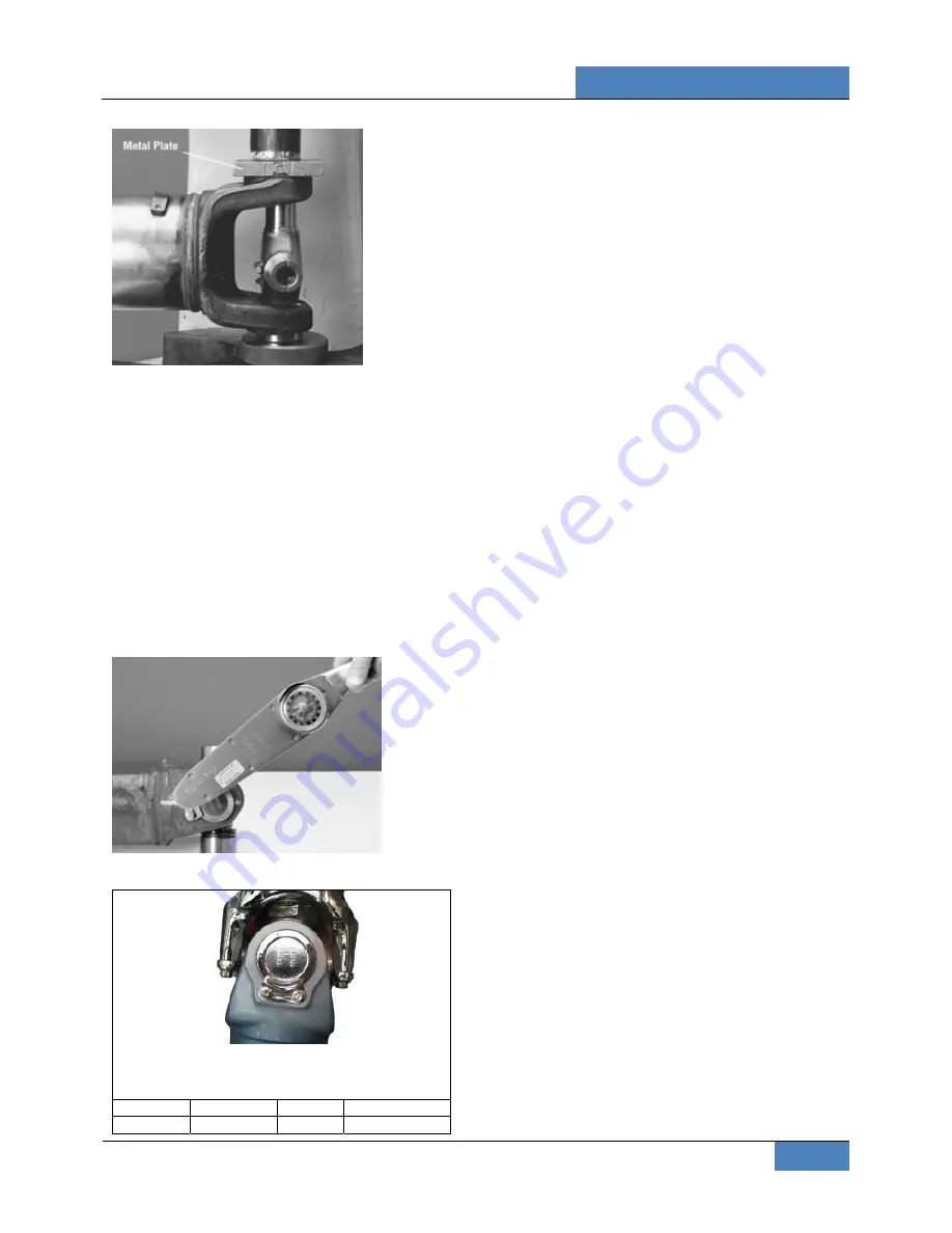
FIGURE 30
5. Flip yoke 180 degrees. Position the
remaining installation height tool on the end
of another bearing cup assembly. Place
bearing cup assembly over trunnion
diameter and align it to the yoke cross hole.
Push the bearing cup assembly until both
installation height tools are flush with the
cross hole face.
6. Install new spring tabs and 8mm thread
bolts. Make sure that no grease or foreign
material is present between the contact
areas of the spring tabs, bearing cups and
yoke cross hole faces. Tighten bolts to the
required torque.
FIGURE 31
SPRING TAB BOLT TORQUE
Bolts are specially heat-treated. DO NOT substitute
inferior grade bolts.
Series
Head size
Size
Bolt torque
SPL250
6 point
8-1mm
25-30 lbf-ft
6. EXPLANATION OF COMMON DAMAGES
1. Cracks: Stress lines due to metal fatigue.
Severe and numerous cracks will weaken the
metal until it breaks.
2. Galling: Scraping off of metal or metal
displacement due to friction between surfaces.
This is commonly found on trunnion ends.
3. Spalling (surface fatigue): Breaking off of
chips, scales, or flakes of metal due to fatigue
rather than wear. It is usually found on splines
and U-joint bearings.
4. Pitting: Small pits or craters in metal surfaces
due to corrosion. If excessive, pitting can lead to
surface wear and eventual failure.
5. Brinelling: Surface wear failure due to the
wearing of grooves in metal. It is often caused by
improper installation procedures. Do not confuse
the polishing of a surface (false brinelling), where
no structural damage occurs, with actual
brinelling.
6. Structural Overloading: Failure caused by a
load greater than the component can stand. A
structural overload may cause propeller shaft
tubing to twist under strain or it may cause cracks
or breaks in U-joints and spline plugs.


