SECTION 12: BRAKE AND AIR SYSTEM
DOB 2490-2789 | X3-45 Commuter PA1605 Maintenance Manual (Final Version – Rev.2 April 2016)
11
not distorted. Particular attention should be
given to long lines. Any supporting component
(clips, ties, grommets, etc.) must be secured to
prevent against unnecessary vibration and
eventual loosening of connection. Any detected
leak should be repaired. Be sure nylon lines are
not near areas of intense heat. Check for any
missing grommets or loose material where
chafing or cutting may occur. Replace with new
material as required. In general, lines should be
securely located in position and free from any
binding condition which would hinder air flow.
10. PRESSURE
REGULATING VALVES
There is one pressure regulator for the belt
tensioners, and another one installed on
vehicles equipped with the World transmission
output retarder.
The other regulator is located in the engine
compartment, on the engine cradle R.H. side
(accessible through the engine R.H. side door).
It is used for transmission retarder and should
be adjusted to 85 ± 3 psi (586 ± 20 kPa).
Air Pressure
(psi)
Air Pressure
(kPa)
Retarder 85
586
10.1 MAINTENANCE
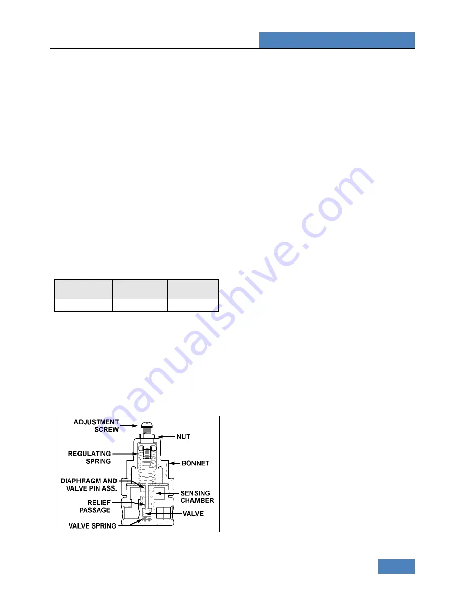
Every 100,000 miles, disassemble the regulating
valve and wash all metal parts in a cleaning
solvent (Figure 12). Examine the diaphragm; if
cracked, worn or damaged, replace with a new
one. If the valve is excessively grooved or pitted,
it should be replaced. Replace any other part
that appears worn or damaged. After reassem-
bly, adjust to the specified pressure setting and
check for air leakage.
FIGURE 12: AIR PRESSURE REGULATING VALVE
12141A
10.2 PRESSURE
SETTING
PROCEDURE
Remove the dust cap from the pressure check
valve (Figure 12). Attach a pressure gauge at
this port and check the pressure reading. If the
pressure reading is incorrect, adjust as follows:
10. Loosen the locking nut, turn the adjustment
screw counterclockwise to decrease
pressure by approximately 10 psi (70 kPa)
below the required pressure.
11. Turn the adjustment screw clockwise to
increase the pressure slowly until the re-
quired pressure setting is reached. Tighten
the locking nut.
12. Remove pressure gauge and replace dust
cap on the air pressure check valve.
11. AIR COMPRESSOR
The Wabco System Saver 636 Twin Cylinder air
compressor is located on the alternator side of
the engine, at the flywheel end (Figure 13). Its
function is to provide and maintain air under
pressure to operate devices in brake and air
systems.
The compressor is driven by the ring gear, and
is water cooled. Engine coolant is fed to the
compressor through a flexible hose tapped into
the block water jacket and connected to the rear
of the compressor. Coolant returns from the top
of the compressor (governor side) through a
flexible hose to the engine pump.
The air is taken from the air intake manifold and
entered in the top of the compressor. The
compressed air is pushed into the discharge line
located on side of the compressor, which sends
air to the air dryer. Lubricating oil is supplied to
the compressor by a line from the cylinder block
oil gallery connected to the air compressor.
Lubricating oil returns to the engine crankcase
through the air compressor drive assembly.
Refer to Wabco 636 Twin Cylinder Service
Documentation for Maintenance and repair
information.


