SECTION 12: BRAKE AND AIR SYSTEM
DOB 2490-2789 | X3-45 Commuter PA1605 Maintenance Manual (Final Version – Rev.2 April 2016)
13
information on this valve is supplied in the
applicable booklet annexed to this section under
reference number SD-03-3611.
FIGURE 15: RD-3
12136
14. FLIP-FLOP CONTROL VALVE (TW-1)
A flip-flop control valve mounted on the L.H.
lateral console is provided to unload tag axle air
springs and to lift tag axle. It is a manually
operated "on-off" valve. Maintenance and repair
information on this valve is supplied in the
applicable booklet annexed to this section under
reference number SD-03-3602.
FIGURE 16: TW-1
12138
15. DUAL BRAKE APPLICATION VALVE
(E-8P)
The E-8P dual brake application valve is a floor
mounted, foot-operated type brake valve with
two separate supply and delivery circuits. This
valve is located in the front service compartment
(Figure 18).
Maintenance and repair information on the E-8P
this valve is supplied in the applicable booklet
annexed to this section under reference number
SD-03-830.
FIGURE 17: E-8P DUAL BRAKE VALVE
15.1
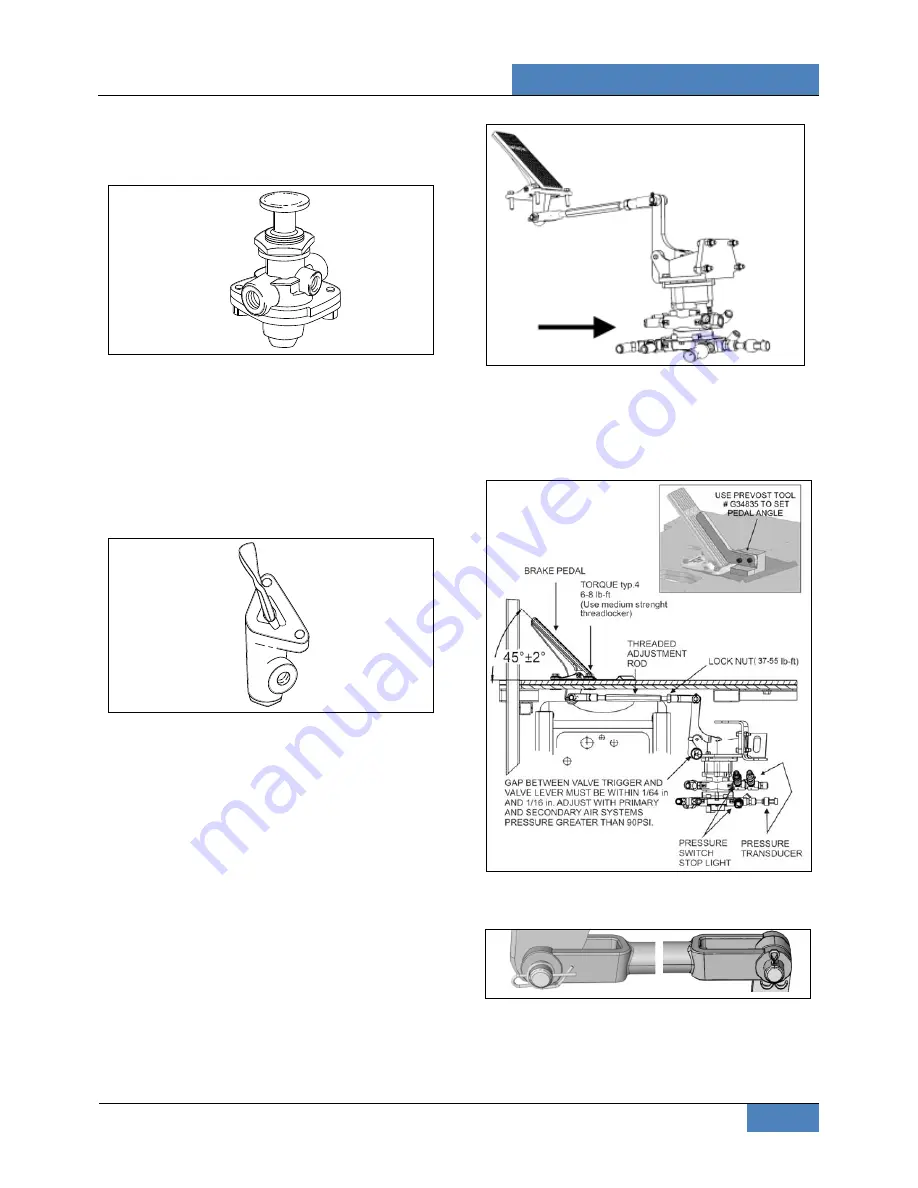
BRAKE PEDAL ADJUSTMENT
After brake pedal replacement or repair, adjust
the pedal to its proper position according to the
following procedure.
FIGURE 18: BRAKE PEDAL ADJUSTMENT
12208_1
1. Connect the linkage yokes and install cotter
pin and ring cotter.
FIGURE 19: PINS
2. Loosen threaded rod lock nut and turn the
threaded rod CW or CCW in order to obtain
a 45
o
brake pedal inclination. Use
Prevost


