SECTION 16: SUSPENSION
DOB 2490-2789 | X3-45 Commuter PA1605 Maintenance Manual (Section 16 revised April 2019)
13
3.1 AIR
SPRINGS
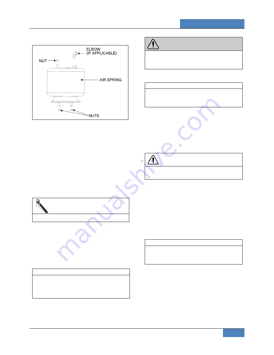
FIGURE 11: AIR SPRING
16052
The air springs are made from a special
compound rubber molded to the proper contour
and dimensions. The entire vertical load of the
vehicle is supported by these springs. Each of
the two axles is provided with air springs that are
attached to the subframe and to the axles.
3.1.1
Inspection
1. Check operation of bellows.
2. Visually inspect bellows for evidence of
cracks, punctures, deterioration, or chafing.
Replace the bellows if any damage is
evident.
MAINTENANCE
Inspect air bellows every 6,000 miles.
3. With the primary air system at normal
operating pressure (95 - 125 psi (655 - 860
kPa)), coat all suspension air line
connections and bellows mounting areas
with a water and soap solution. Bubbles will
indicate an air leak, and none is
permissible. Repair or replace defective
parts.
NOTE
If air spring is removed from vehicle, bellows
can be lightly inflated and submerged in water
to detect any leakage. If any leakage is
detected, replace bellows.
WARNING
To prevent personal injury, do not apply more
than 10 psi (69 kPa) of air pressure to the
uninstalled air spring.
3.1.2
Removal
NOTE
Suspension air springs (drive and tag axles)
can be removed without removing the entire
axle assembly.
1. Safely support vehicle at the recommended
body jacking points. To gain access to a
given air spring, the corresponding wheel
can be removed as follows.
a) Jack vehicle until the tire clears the
ground, and place safety supports
underneath body.
CAUTION
Only the recommended jacking points must be
used as outlined in Section 18, “Body”.
b) Support the axle with a suitable hydraulic
floor jack at the recommended jacking
point.
c) Remove wheel.
2. Exhaust compressed air from accessory air
tank by opening drain cock under reservoir.
3. Disconnect the height control valve link and
pull down the overtravel lever to ensure all
air is exhausted from air springs.
NOTE
While performing this step, do not change the
height control valve overtravel lever
adjustment.
4. Disconnect air line from air spring, remove
elbow (if applicable), and cover both the line
end and fitting to prevent the entry of foreign
matter.
5. Remove the air spring upper nut, and then
the two lower nuts. Remove air spring.
3.1.3
Installation
1. Compress air spring as necessary, then
aligning studs with their holes, position air
spring between both the lower and upper


