SECTION 22: HEATING AND AIR CONDITIONING
42
DOB 2490-2789 | X3-45 Commuter PA1605 Maintenance Manual (Final Version – Rev.2 April 2016)
7.14 LEAK TESTING
Some methods such as nitrogen pressure, soap
and electronic sniffer can be used for leak
testing.
8. CENTRAL HEATING SYSTEM
As seen earlier in this section, the vehicle
interior is pressurized by its Heating, Ventilation
and Air Conditioning (HVAC) system. The
vehicle interior should always be slightly
pressurized to prevent cold and moisture from
entering. Air flow and controls divide the vehicle
into two areas: driver’s area and passengers’
area.
The schematic of Figure 2 shows the heating
system with its components.
8.1 DRAINING
HEATING
SYSTEM
To drain the entire system, refer to Section 05,
“Cooling
”. If only the driver’s or main heater core
must be drained, refer to the following
instructions.
Draining Driver’s Heater Core
1. Stop engine and allow engine coolant to
cool.
2.
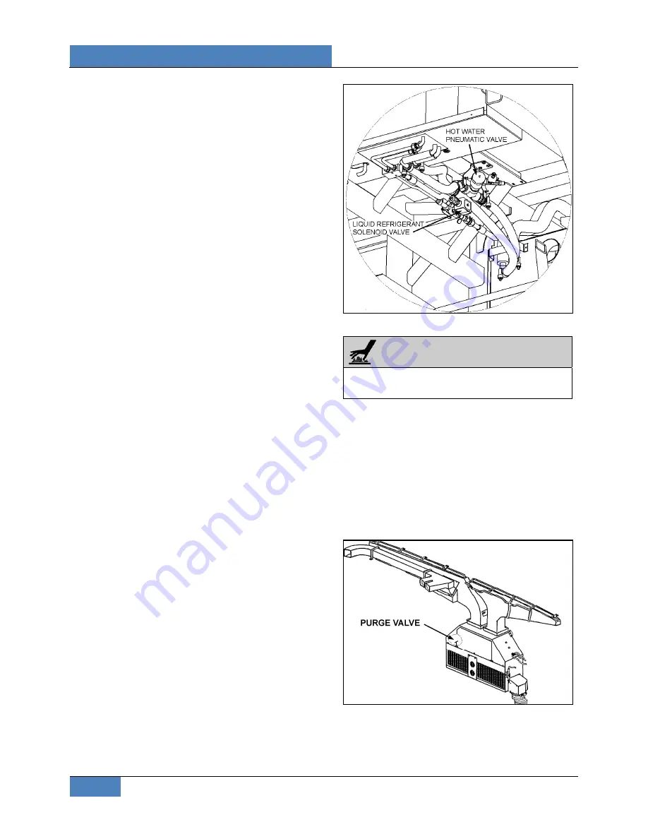
Locate the normally open hot water
pneumatic valve on the ceiling of the spare
wheel compartment (Figure 48), disconnect
its wiring connector, and then connect a 24-
volt external power source, using jumper
cables, to close valve.
3. Close the hot water lines shut-off valves
located next the engine on street side (see
Figure 2 & Figure 52).
FIGURE 48: CEILING OF THE SPARE WHEEL
COMPARTMENT
WARNING
Before proceeding with the following steps,
check that coolant has cooled down.
3. Loosen hose clamp, install an appropriate
container to recover coolant, and
disconnect silicone hose from hot water
solenoid valve.
4. From inside of vehicle, remove the two
finishing panels in front of unit. Remove the
three screws fixing the unit front panel.
Open the manual vent located inside the
driver’s HVAC unit, on the driver’s side
(Figure 49) to ensure an efficient draining.
FIGURE 49: DRIVER'S HVAC/DEFROST UNIT


