background image

XTR-PX2-C0006-IN004 Console and Software


          14 


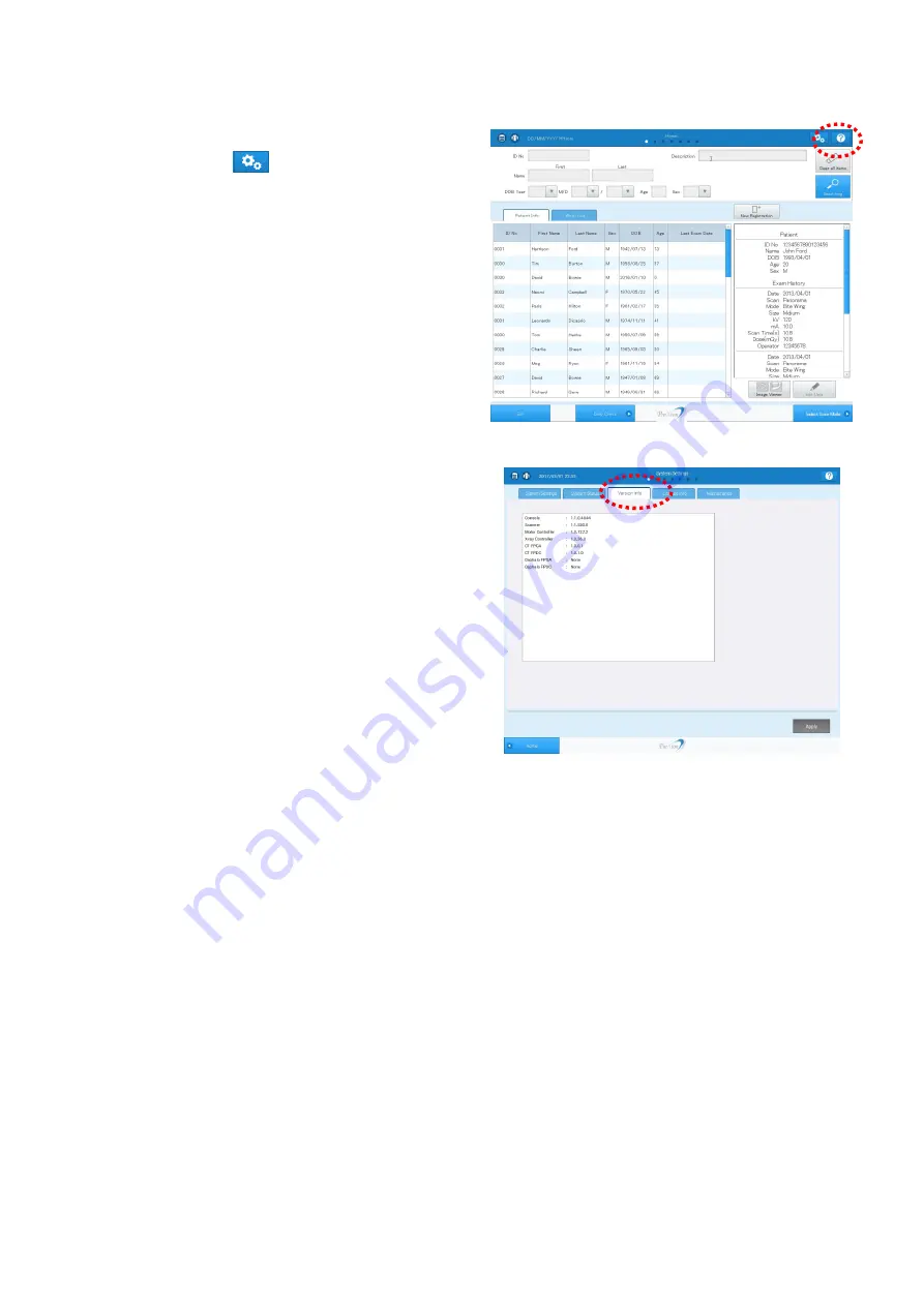
Step-6: Confirm the software version from the Console   


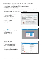
(1) . Start up the Console software,   

and click the 

  (System setting button). 


(2). 

The “System Settings” screen appears.   

Select the “Version Info” tab. 


        Please confirm the program files are updated. 


Summary of Contents for PreXion3D Excelsior

Page 1: ...IN004 Cover Page i edition 004 3rd July 2017 Stand Scanner Unit Console and Software Cephalometric option X ray room door interlock leveling without Stand Appendix1 model changes after 0076 Appendix2...

Page 2: ...owing two labels inside the equipment Symbol Meaning Protective Earth Caution about High Voltage ii specification of the equipment Regarding the specification of PreXion3D Excelsior refer to chapter 7...

Page 3: ...ing the STAND BASE 5 3 5 Attach NUT with NUT HOLDER on the BASIC FRAME 16 locations 6 3 6 Build BASIC FRAME on the STAND BASE 6 3 7 Attach STAND PLATE TOP on the top of BASIC FRAME with 4 screws tight...

Page 4: ...g 242 lbs Weight base plate only 50kg 110 lbs 1 2 contents This is two layers packing lower layer upper layer Bar for the Ceph option is not included 1 3 not included in the packing The Grip for the b...

Page 5: ...TR PX2 C0006 IN004 Stand 3 1 4 main parts STAND BRACKET TOP WALL PLATE STAND BRACKET BOTTOM STAND BRACKET MIDDLE 2 STAND PLATE TOP BASIC FRAME GRIP 4 Service tool STAND BASE HEAVY BRACKET 4 ADJUSTER 6...

Page 6: ...pace 2 2 wall anchor vertical position board anchor position 2 3 wall anchor horizontal position left right symmetry position 100 10 mm 1000 10 mm According to the position of STAND BRACKET height can...

Page 7: ...blanket Remove the upper layer package attach the Grip on the STAND BASE 4 locations Take out the STAND BASE Attach the ADJUSTER by hand 6 locations Note This process is done in the factory Among 6 a...

Page 8: ...n the surface And slide them to the proper location Place NUT in the upper side surface side on the HOLDER Caution BASIC FRAME has top and bottom direction On the top surface screw holes are tapped fo...

Page 9: ...ur screws 3 9 Confirm the wall fixing point and screw the BOARD ANCHOR into the wall plate in total 10 locations for top middle and bottom 3 10 Affix the wall BRACKET by board anchor screws with washe...

Page 10: ...16 D CP8X30 I3 CM1 10 STAND BRACKET BOTTOM x4 STAND BRACKET TOP x2 STAND PLATE TOP x4 E WASHER W4 10 for wall F WALL ANCHOR SCREW 10 for wall G NUT and others 16 STAND BRACKET MIDDLE x4 WALL PLATE x4...

Page 11: ...optional 3 20 4 Wiring 4 1 5 Confirming stand alone operation Control panel operation 5 1 6 Connecting the Console 6 1 6 1 Connecting the Scanner and the Console 6 1 6 2 Connecting the Scanner and th...

Page 12: ...pace for unpacking the device PreXion3D Excelsior is delivered from the factory in the following packing specification You will need a space to unpack it If your device comes with a Cephalometric Sens...

Page 13: ...contents Label Image Pallet No Box No Name 1 1 ARM PILLAR ASSY BOX 1 1 FIXED ARM COVER BOX 2 ROTARY ARM ASSY BOX 5 ACCESSORY BOX 2 3 CHINREST ASSY BOX 4 DC PILLAR BOX 6 ROTARY ARM COVER 1 BOX 7 PILLAR...

Page 14: ...e device when it is extended to the very top of the gantry in the following five stages 2 220 mm 2 170 mm 2 120 mm 2 070 mm 2 020 mm For all heights the lowest point when the gantry is lowered to the...

Page 15: ...x 30 H mm weight approximately 900 g Mouse Approximately 64 W x 112 D x 36 H mm weight approximately 90 g Display Approximately 446 W x 147 D x 380 H mm weight approximately 5 800 g Normally the Expos...

Page 16: ...are an X ray Scanner room that has the space for installing the Scanner listed in 1 2 Size of the installation space Also place the Console outside the X ray room Arrangement example Emergency stop sw...

Page 17: ...ground the device 3 Installing the additional breaker The PreXion3D Excelsior is a permanently installed device and is supplied power by the distribution board in the building To ensure safety connect...

Page 18: ...C100 240V 50 60Hz 700W or lower Display AC100 240V 50 60Hz 100W or lower 1 7 Floor load capacity The floor must be able to withstand the weights of the device without the Cephalometric Sensor Unit 165...

Page 19: ...ter D Length L Diameter of drill Depth of drill 1060 M10 14 5 mm 60 mm 15 0 mm 67 5 mm Fixing bolt Hexagon socket head M10 By fixing the anchors the pull out force of the anchor bolts achieved is 7 00...

Page 20: ...mm to 171 5 mm Installing the Anchor The anchor attachment work needs to be performed before taking possession of the device Making holes in the concrete floor recommended tool Kanzawa drill guide K...

Page 21: ...vent the device from vibrating and ensure a high image quality Mount the below wall fixing brackets to the device column and secure it to the wall with four screws Tensile strength required for the sc...

Page 22: ...1 BOLT M8X35 4 WASHER M8 4 AIR PACKING 400X400 1 AIR PACKING 700X1200 1 PLASTIC BAG 300X450 2 1 1 FIXED ARM COVER BOX PART NAME QTY FIXED_COVER_TOP 1 FIXED_COVER_BOTTOM 1 FIXED_COVER_RL 1 PLASTIC BAG...

Page 23: ...LEBAR 1 CHINREST UNIT 1 SENSOR BASE 1 WALL BRACKET 1 CHINREST 1 LIFTING COVER TOP BRACKET R 1 PART NAME QTY LIFTING COVER TOP BRACKET L 1 PILLAR MECHA STOP 2 1 PILLAR MECHA STOP 3 1 PLASTIC BAG 80X120...

Page 24: ...PLASTIC BAG 460X600 1 AIR PACKING 400X700 1 3 CHINREST ASSY BOX PART NAME QTY CHINREST ASSY 1 CHINREST_COVER_TOP 1 CHINREST_COVER_BOTTOM 1 COVER CUSHION 850x650x1 2 PLASTIC BAG 460x600 2 SCREW ASSY E...

Page 25: ...R CUSHION 850x850x1 2 PP BAND 2 PP BAND STOPPER 2 6 FIXED ARM COVER BOX PART NAME QTY ROTARY_COVER_TB 1 ROTARY_COVER_TF 1 ROTARY_COVER_BOTTOM 1 X RAY_COVER_OUT 1 PLASTIC BAG 900x800 3 PLASTIC BAG 650x...

Page 26: ...ASTIC BAG 300X450 1 PLASTIC BAG 460x600 1 PLASTIC BAG 650x800 3 COVER CUSHION 850x650x1 4 8 ROTARYARMCOVER2BOX PART NAME QTY X RAY_COVER_IN 1 FPD_COVER_IN 1 FPD_COVER_OUT 1 PLASTIC BAG 650x800 1 PLAST...

Page 27: ...the Stationary Arm 3 3 Attach the SENSOR BASE 3 4 Wiring to the SWITCH Box 3 5 Attaching the SWITCH Box 3 6 Attaching the cover FIXED COVER BOTTOM only 3 7 Attaching the Rotation Arm 3 8 Attaching th...

Page 28: ...e buried into the floor properly Fixing the PILLAR to the floor Fix the PILLAR with CP10X40 CM1 x4 Screw bag S Tightening torque 25 N m Disposing the protection sheet To protect the base of the PILLAR...

Page 29: ...25 I3 CM1 x2 Screw bag R Fixing the PILLAR to the wall Fix the wall fixing bracket with bolts M10 hexagon socket head cap screw x4 Tightening torque 25 N m Securely tighten the CP6X25 I3 CM1 Tightenin...

Page 30: ...XTR PX2 C0006 IN004 3 4 3 2 Attaching the Stationary Arm Place the Stationary Arm on the PILLAR and secure it with the fixing bolts x6 Screw bag R Tightening torque 5 1 N m CP6X25 I3 CM1...

Page 31: ...y to the PILLAR CP5X12 I3 CM1 x2 Screw bag M 2 Attach the mechanical stopper 2 and mechanical stopper 3 When attach the mechanical stopper 2 do not attach the screw to the center of three screw holes...

Page 32: ...04 3 6 3 Attach the Lift jig Disconnect the cable 40 at the left side of the PILLAR and connect the cable of the Lift jig Connect the power cable of the Lift jig to the power source Connect to the cab...

Page 33: ...curely tighten the screws of the SENSOR BASE The SENSOR BASE fixed at a tilt will hit and break the photo interrupter attached on the back of the PILLAR Pay careful attention to perform the installati...

Page 34: ...ergency stop switch Earth Door Interlock optional View from the top of SWITCH Box View from the side of SWITCH Box System main switch Terminal block Earth cable No 123 Earth cable No 104 Insertion hol...

Page 35: ...where power cable will be connected WAGO terminal When an electrician of the facility will perform the AC power wiring operation tell them these L N E terminals are the connection points Actual AC pow...

Page 36: ...M1 x2 Screw bag H Fix the LAN cable with the clamp 4 Insert the cable of the emergency stop switch in the SW BOX and fix it with the fixture BUSHING SR5N 4 Use a plier manufactured by Heyco PN3X10 P3...

Page 37: ...SWITCH Box on the back of the PILLAR with the PN3X10 P3 CM1 x2 Screw bag H After attaching the SWITCH Box attach the cover on the top of the SWITCH Box with TR4X10 CM1 x4 the top cover and screws are...

Page 38: ...otation Arm attach the cover FIXED COVER BOTTOM Fix the bottom side with the TR4x10 CM1 x4 Fix the left and right side with the TR4x10 CM1 x4 At this time be sure to attach the FIXED COVER BOTTOM Afte...

Page 39: ...ching the Rotation Arm Attach the Rotation Arm by using the positioning jig and the Lift jig 1 Remove the cable cover bracket 2 Remove the edge saddle for cable protection 3 Move up the arm with the L...

Page 40: ...Rotation Arm to the packing materials 6 For preparation of attaching rotate the couplings with your hands to move the Rotation Arm to the center of the hole Coupling Coupling BOLT M8X35 WASHER M8 Whe...

Page 41: ...r hand and align the hole position with viewing the connection part from the top Check that the X ray tube is at the right side and the FPD is at the left side viewed from the front X ray tube FPD Whe...

Page 42: ...the fixing position Prepare a stepladder hold the Rotation Arm with your hand and align the hole position with viewing the connection part from the top When we use STAND we cannot put the container b...

Page 43: ...nly one bolt excessively 10 Remove the positioning jig and temporarily attach the fixing bolts CP5X25 I3 CM1 x3 Screw bag Q to the same position Tighten three bolts evenly If you rotate one bolt two t...

Page 44: ...XTR PX2 C0006 IN004 3 18 12 Attach the edge saddle 13 For preparation of wiring rotate the couplings with your hands to move the mount of the Rotation Arm Edge saddle Coupling Coupling...

Page 45: ...cover bracket This bracket is attached later 2 Attach the CP5X20 I3 CM1 x2 Screw bag O to the PILLAR and then the Chin Rest Arm while rotating the Chin Rest Arm Tightening torque 3 0 N m 3 Fix the Chi...

Page 46: ...XTR PX2 C0006 IN004 3 20 3 9 Attaching the LCD Secure the LCD on the Chin Rest Arm with the PN4X8 P3 CM1 x4 Screw bag J 3 10 Attaching Cephalometric Sensor Unit optional TBD PN4X8 P3 CM1...

Page 47: ...ring the power cable Pass through the power cable No 104 to the clamp Connecting to the noise filter Loosen the screws of the noise filter Connect the power cables x3 and screw them Close the clear co...

Page 48: ...osure Switch on the hook to fix Attach the earth cable Attach the earth cable No 109 to the base stand Take out the terminal block from inside the SWITCH Box and pass it by the side of the noise filte...

Page 49: ...le Put the cable through the clamp to fix The three nylon clamps from left side are the PILLAR clamp the LCD panel clamp and the chin rest arm Assy clamp Fix all the cables from the cable veyor of the...

Page 50: ...PX2 C0006 IN004 4 4 Fixing the power cable Noise filter Fix the power cable to the noise filter Close the noise filter cover Connecting the cable Connect the cables x5 on the PILLAR side Cover Power c...

Page 51: ...XTR PX2 C0006 IN004 4 5 Fixing the cable Fix the cable on the Chin rest side with the clamp Fixing the cable Fix the cable 97 with the clamp...

Page 52: ...earth wire Fixing the cable Attach the earth wire No 110 to the Chin rest Fix the cables 96A 96B with the clamp Connecting the connector Connect the connectors x3 to the power circuit board PN3x10 P3...

Page 53: ...TR PX2 C0006 IN004 4 7 Connecting the connector Connect the connectors x5 in the Chin Rest Arm Attaching the cover bracket Use the PN3x10 P3 CM1 x4 to attach the cover bracket COVER BRACKET CHIN ARM 2...

Page 54: ...XTR PX2 C0006 IN004 4 8 Removing the cable tie Cut and remove the cable tie fixing the laser...

Page 55: ...USB connector out of the Stationary arm body Connect the LCD cables x3 to the connectors and push the connector of the USB cables into the housing Attach the bracket and then fix the LCD cables x3 wit...

Page 56: ...rt at the back side Checking wiring Move the part on which the horizontal laser Frankfurt horizontal beam is attached up and down to check that the bracket plate does not come in contact with other ca...

Page 57: ...g the protection for the cables Cut the cable tie and discard it together with the plastic bag Laying the cable Remove the foam padding Put the cables those are on the Stationary Arm through the hole...

Page 58: ...PD holder bracket Remove the PN3x8 P3 CM1 x4 and detach the FPD holder bracket Keep the detached FPD holder bracket for later possible relocation Removing the FPD protection sheet Lift up the FPD with...

Page 59: ...B 3 0 cable Move the Rotation Arm to convenient position easy for wiring work Put the USB 3 0 cable though the hole of the arm and fix it with a clamp Connecting the connector Connect the connector of...

Page 60: ...rotational ram Colors and the number of the cables are as shown below Unfixing the cables Cut the cable tie to unfix the cables white x4 Green White Blue Yellow X ray tube FPD Target connector x7 Targ...

Page 61: ...04 4 15 Unfixing the cables Cut the cable tie to unfix the cables white x3 Connecting the connector white Connect the connectors of the cables white x7 Access and connect the connector from the inside...

Page 62: ...he cables yellow x4 Connecting the connector green Connect the connectors of the cables green x1 Connect the connector of the cable yellow Take the cable on the PSC board side out of the inside of the...

Page 63: ...ing the earth wire Fix the earth wire of the cable green to the Rotation Arm Laying the USB3 0 cable Take the USB3 0 cable out of the hole of the Rotation Arm and lay the cable toward the Stationary A...

Page 64: ...Attach the CABLE COVER with the PN3x10 P3 CM1 x4 76 Fixing the cable Fix the LCD cable with a cable tie To avoid contacting the cover fix the cables with the cable tie with the lock part at the back...

Page 65: ...t a remaining part of the cable tie 74 Fixing the cable Fix the LCD cable with cable ties x5 Attach the cable tie to the CABLE COVER and fix it Cut a remaining part of the cable tie 73 CABLE_USB 3 0 C...

Page 66: ...of about two fingers is ensured short circuit test before AC power cable wiring operation AC power cable wiring operation While power switch on the Switch Box is off in the presence of an electrician...

Page 67: ...ency stop switches x2 have been released and power on the scanner 2 Press and hold the button of the LCD 3 Enter the password and press the Confirm button 4 Operate all buttons to check that the Scann...

Page 68: ...hange as below E_ALT1 E_ALT2 DMSW DoorLock 6 Check potentiometer value Click Get PotentioVal when the rotation arm is at the home position and check that the value is within the range of 1500 to 2500...

Page 69: ...CD display Chk2 Version information Internal hardware connection status Check the potentio value Within the range of 1500 to 2500 at the home position Output test Sensor information Page scroll Motor...

Page 70: ...C0006 IN004 5 4 LCD display Chk3 LCD display Chk4 F W update Restore IP address Backup Restore the MTC data Update parameter file ARM home position setting FPD trigger signal check FPD home position...

Page 71: ...fer to the Console and Software installation manual 6 2 Connecting the Scanner and the Console Power ON the Console PC and the monitor In the Windows log on screen enter prexion in the password column...

Page 72: ...1 Performing daily check Pay attention not to place any objects in the X ray field 1 Power on the Scanner 2 Start up the Console software and click the System setting button 3 The System Settings scr...

Page 73: ...5 The Maintenance screen appears Press the Clear the results button of the Common tab and then press the Normal ALL Func button to check that the Scanner works properly Wait to complete the daily chec...

Page 74: ...angle Colli Calib and Panorama Alignment 1 The Maintenance screen appears Select the Collimator tab 2 Click Colli Calib button Initialization of the Scanner starts 3 Wait for that the initialization o...

Page 75: ...XTR PX2 C0006 IN004 7 4 4 Click Panorama Alignment 5 Wait for that the status indicator changes from green to blue and from blue to green 6 Press the Exposure Switch to emit X ray...

Page 76: ...the displayed value and go to the next step When Panorama Alignment process takes time and it does not finish go to 7 10 When adjustment work does not finish 8 Enter the value recorded in your memo in...

Page 77: ...Small Alignment 2 Wait for that the status indicator changes from green to blue and from blue to green 3 Press the Exposure Switch to emit X ray 4 A displacement is automatically calculated and the re...

Page 78: ...tment in horizontal direction Loosen the fixing screw for horizontal For DIRECTION LEFT Loosen the adjustment screw According to the value displayed on the screen loosen the adjustment screw For DIREC...

Page 79: ...indicator changes from green to blue and from blue to green 8 Press the Exposure Switch to emit X ray 9 A displacement is automatically calculated and the result value is displayed If OK go to 7 3 Att...

Page 80: ...Clear the results button of the Common tab and then press the Normal ALL Func button to check that the Scanner works properly Wait to complete the daily check 7 4 Attaching the Geometry phantom Small...

Page 81: ...4 7 10 7 5 Adjusting geometry FPD Center 1 Select the Geometry tab 2 Click XY Offset Reset 3 Click Calibrate Geometry 3 Wait for that the initialization of Scanner is completed and the status indicato...

Page 82: ...meter is automatically updated wait time 4 to 5 minutes When OK press the Enter key of the Console to close the screen and perform 7 7 Adjusting geometry Center of the Rotation XY If NG take a memo of...

Page 83: ...XTR PX2 C0006 IN004 7 12 7 6 Adjusting FPD Tilt 1 Lift up FPD and secure it from the rear with the screws 2 Remove the screws x2 and then the bracket at the flame bottom Remove the bracket...

Page 84: ...racket at the frame bottom that was removed in step 2 How to adjust the screw 1 Fix the adjustment screw by a hexagon wrench 2 Loosen the nut by a screw wrench 3 Turn the adjustment screw Only by the...

Page 85: ...XTR PX2 C0006 IN004 7 14 7 7 Adjusting geometry Center of the Rotation XY 1 Click Calibrate XY Offset Reset 2 An internal processing start Please wait one to two minutes to finish...

Page 86: ...XTR PX2 C0006 IN004 7 15 7 8 Detaching the Geometry phantom Small sphere phantom 1 Detach the Geometry phantom from the chine rest arm...

Page 87: ...PX2 C0006 IN004 7 16 7 9 Adjusting the panorama offset 1 Select the Collimator tab 2 Click ColliCalib 3 Wait for that the initialization of Scanner is completed and the status indicator changes to Gr...

Page 88: ...ma Offset 5 Wait for that the status indicator changes from green to blue and from blue to green 6 Press the Exposure Switch to emit X ray 7 A displacement value is automatically calculated and the pa...

Page 89: ...rm the following measures 1 Remove the connectors x2 and screws x4 and then remove the collimator assembly 2 Return to the initial screen Common tab of the maintenance mode place a checkmark to the Co...

Page 90: ...LIFTING COVER BOTTOM 4 FIXED COVER RU 5 FIXED COVER TOP 6 FIXED COVER FU 7 FIXED COVER RL 8 FIXED COVER RR 9 FIXED COVER FD 10 CHINREST COVER TOP 11 CHINREST COVER BOTTOM 12 FPD COVER OUT 13 FPD COVER...

Page 91: ...R L Attach the LIFTING COVER TOP BRACKET R L with the TR4x10 CM1 x2 for each Disassembling the LIFTING COVER Remove the PN3X6 P3 CM1 x6 and disassemble the LIFTING COVER 61 PN3X6 P3 CM1 LIFTING COVER...

Page 92: ...BOTTOM with the TR4x10 CM1 x4 Use the protection sheet for base Refer to Page 3 2 Attaching the LIFTING COVER BOTTOM BRIDGE Attach the LIFTING COVER BOTTOM BRIDGE and fix it with the PN3X6 P3 CM1 x6...

Page 93: ...COVER TOP Attach the LIFTING COVER TOP and fix it with the PN3X6 P3 CM1 x4 Screw bag G After attaching the LIFTING COVER TOP move the gantry up and down and check that the clearance of the cover has b...

Page 94: ...e PC SHEET A B and fix them with the PN3X6 P3 CM1 x1 for each Screw bag G Attach it after peeling off the film on the surface of PC SHEET The screws to be fixed here are used only at the locations sho...

Page 95: ...TR4x10 CM1 x6 Attaching the Laser position adjustment knob Be careful to not let the washer fall off Attaching the CHINREST COVER TOP Attach the CHINREST COVER TOP and fix it with the TR4x10 CM1 x4 TR...

Page 96: ...with the TR4x10 CM1 x4 Attaching the FIXED COVER RU Attach the FIXED COVER RU and fix it with the TR4x10 CM1 x4 First fasten the upper two screws and then the lower two Attaching the FIXED COVER RL A...

Page 97: ...3 Attaching the CHINREST COVER BOTTOM Attach the CHINREST COVER BOTTOM and fix it with the TR4x10 CM1 x4 Moving the Chinrest downward makes it easier to attach the CHINREST COVER BOTTOM Align the Chin...

Page 98: ...ARY COVER BOTTOM Attach the ROTARY COVER BOTTOM Fix the side face with the TR4x10 CM1 x6 and the bottom with TR4x10 CM1 x4 Attaching the FPD COVER IN Attach the FPD COVER IN and fix it with the TR4x10...

Page 99: ...RAY COVER IN Attach the X RAY COVER IN and fix it with the TR4x10 CM1 x4 Attaching the ROTARY COVER TB Attach the ROTARY COVER TB Attaching the ROTARY COVER TF Attach the X RAY COVER TF and fix it wit...

Page 100: ...the FPD COVER OUT and fix it with the TR4x10 CM1 x4 Attaching the X RAY COVER OUT Attach the X RAY COVER OUT and fix it with the TR4x10 CM1 x4 The cover is finished with lead resulting in a heavy par...

Page 101: ...XTR PX2 C0006 IN004 8 12 8 2 Attaching the Handgrip Fix the Handgrip with the PN4x10 P3 CM x2 Screw bag K PN4x10 P3 CM 1 Attaching orientation of hand grip...

Page 102: ...ARM 2 Fix the CHINREST UNIT with the CP5x20 P2 CM1 x2 Screw bag P 3 Move the BASE COVER downward Fixing the BASE COVER Fix the BASE COVER with the TR4X10 CM1 x3 Attaching the CHINREST Attach the CHIN...

Page 103: ...Dailycheck tab of Maintenance mode We add Xray Dose Count area During Dailycheck operation by clicking Normal All Func button x ray dosage is measured automatically We should take care not to place a...

Page 104: ...MSN5 2KMN00119 1 Laser Frankfurt horizontal beam WASHER SW5 2KML00091 1 B ANCHOR BOLT 2KML00110 4 Floor fixation C ANCHOR BOLT 2KML00110 4 Wall fixation D BUSHING SR5N 4 2KMN00142 1 Exposure Switch E...

Page 105: ...I PN3X15 P3 CM1 2KML00026 4 Mechanical stopper 3 SENSOR BASE J PN4X8 P3 CM1 2KML00065 4 LCD panel Assy K PN4X10 P3 CM1 2KML00031 2 Handgrip L PN4X15 P3 CM1 2KML00034 1 Earth of the Stationary Arm M C...

Page 106: ...X25 I3 CM1 2KML00018 6 Rotation Arm R CP6X25 I3 CM1 2KML00021 8 Stationary Arm S CP10X40 P2 CM1 2KML00040 4 PILLAR How to read the part names 10 2 Cable ties proved with the product Parts Name Parts N...

Page 107: ...tection of the metal covers from being scratched Paper tape for protection of the metal covers from being scratched Camera Position Adjustment Jig PreXion Step Ladder for viewing the Rotation Arm conn...

Page 108: ...XTR PX2 C0006 IN004 10 5 blank page...

Page 109: ...are MTC XRC CT FPD abd Scanner PC 9 Step 1 Start Tight VNC and open manitenance mode screen Chk3 9 Step 2 copy new program files to Ramdisk area from USB memory 10 Step 3 Update MTC firmware and XRC f...

Page 110: ...een PC and the scanner unit 1 3 service tool TrueImage 2017 TrueImage data Service HASP key TrueImage data is stored in Blu ray Disc The Blu ray Disc is delivered from Japan The data should be shared...

Page 111: ...to LAN port on the NIC Not on the Mother board but on the NIC Monitor cable should be inserted to the far left port of the upper M2000 board There are two M2000 boards in Console PC In case of V1 3 1...

Page 112: ...data to C drive 1 Insert the USB on the Console PC The USB contains TrueImage 2 BootDisc TrueImage 2017 insertion Turn on the power of PC and immediately insert BootDisc for TrueImage 2017 3 Push F12...

Page 113: ...ge becomes ready 6 Wait for initial screen of Acronis one minutes and select Recovery 7 select Disk Recovery click it 6 Archive selection with using Browse button locate the tib file in USB memory T58...

Page 114: ...004 Console and Software 6 6 Click Next 7 Recovery method select Recover whole files and partitions and click Next 8 What to Recover check Disk 1 and click Next 9 Destination of Disk 1 select Disk 1 a...

Page 115: ...0 Caution Message click OK 11 Finish Summary summary screen appears click Proceed button right bellow 12 Data Recovery waiting the operation for seven minutes 13 End message click OK 14 Finish Acronis...

Page 116: ...utton locate the tib data in USB memory T5810_win10_Viewer_Cnsl_20170106_ drive_cef_full_b1_s1_v1 tib for recovery 8 What to Recover select Disk 2 and Disc 3 click Next 9 Destination of Disk 2 select...

Page 117: ...operation Step 1 Start Tight VNC and open maintenance mode screen Chk3 On the Console PC start Tight VNC Tight VNC is located in C Program Files TightVNC The file name is tvnviewer exe And enter 192 1...

Page 118: ...192 168 5 6 ramdisk with using Explorer 2 copy program files to Ramdisk area copy MTC firmware Motor_Control_ cyacd copy XRC firmware XrayCtrl_ cyacd copy CT FPD firmware PX2_CT_P1_ mcs in case of V1...

Page 119: ...XTR PX2 C0006 IN004 Console and Software 11 Step 3 Update MTC firmware and XRC firmware On the Tight VNC screen Click MTC FW button and XRC FW button Wait a few minutes and confirm SUCCESS message...

Page 120: ...XTR PX2 C0006 IN004 Console and Software 12 Step 4 Update CT FPD firmware On the Tight VNC screen Click CT FPGA button The status will change to Reset Erasing then Write Wait SUCCESS message...

Page 121: ...atically after updating the Scanner software and VNC connection will break In case of V1 4 0 0 or later please wait 80 secconds unitil you see the following screen on LCD Now updating message appears...

Page 122: ...are 14 Step 6 Confirm the software version from the Console 1 Start up the Console software and click the System setting button 2 The System Settings screen appears Select the Version Info tab Please...

Page 123: ...Name and Station Name In maintenance mode of scanner unit select Product tab enter Institution Name and click Set And enter Station Name and click Set 4 2 time and date 4 3 Caution 4 3 1 network sett...

Page 124: ...irus software 4 3 3 Windows update Don t perform Windows Update 5 System test Perform one CT scan any condition one Pano scan any condition and one Ceph exposure and confirm the image is generated app...

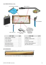
Page 125: ...les 2 2 10 2 14 Fixing Cables 2 11 2 15 Adjusting the Attaching Angle of CEPHALO ASSY 1 2 12 2 16 Adjusting the Attaching Angle of CEPHALO ASSY 2 2 12 3 Ear Rod sencor and Firmware 3 1 3 1 Checking Ea...

Page 126: ...PART NAME QTY CEPHALO BOX 1 1 1 CEPHALO BOX upper side PART NAME QTY CARPAL PLATE ASSY 1 CEPHALO TOP COVER 1 CEPHALO BOTTOM COVER 1 PLASTIC BAG 460X600 1 PLASTIC BAG 650X800 2 COVER CUSHION 850X650X1...

Page 127: ...NAME QTY UNDER COVER 1 CEPHALO CABLE COVER 1 ASSY FPD 1 PLASTIC BAG 650X800 1 COVER CUSHION 850X650X1 1 HMT INSULOK AB190 1 2 STAND BAR BOX Note that this STAND BAR BOX is shipped separately from the...

Page 128: ...the Cephalometric sensor unit To prevent a falling over the main unit attach the STAND BAR with screw CP10X60 CM1 x3 before assembling the Cephalometric Sensor Unit Attach an adjuster to the end of th...

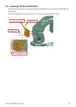
Page 129: ...BASE Aligning with the positioning pin attach the CEPHALO ARM BASE to the Gantry with the CP8X30 CM1 x4 Screw bag F Tighten the tilt adjustment screw CP8X30 CM1 x1 Screw bag F of the CEPHALO ARM CP8X...

Page 130: ...der so that it is not tilted When the connection part of CEPHALO ASSY has been inserted into the CEPHALO ARM BASE you can release your hand from the CEPHALO ASSY Check that the CEPHALO ASSY is inserte...

Page 131: ...XTR PX2 C0006 IN004 Ceph option 2 4 2 6 Removing Tape Remove the tape x7 that is securing the EAR ROD BASE Tape Tape Tape...

Page 132: ...d the other one is for the right ear For the right ear Labeled with an X sticker There is a ring inside the cone See below For the left ear Labeled with a Y sticker There is a pin inside the cone See...

Page 133: ...2 8 Attaching UNDER COVER After positioning the EAR RODs to the innermost sides attach the UNDER COVER to UNDER COVER BRACKET with the PN3X6 P3 CM1 x3 Screw bag C UNDER COVER BRACKET UNDER COVER PN3X...

Page 134: ...There are balls embedded inside the nose support FOREHEAD BASE Check that the balls have been embedded when taking it out of the packing box 2 10 Attaching CEPHALO BOTTOM COVER Attach the CEPHALO BOTT...

Page 135: ...to let the FPD fall during work To prevent the FPD surface from being scratched install the FPD as it is wrapped around the cushion seat When attaching the FPD unit pull out the cables before startin...

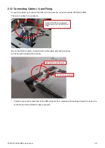
Page 136: ...d in Secure the USB 3 0 cable connector part not the cable part with a cable tie Cut off the extra length of the cable tie In order to prevent the metal part of the USB connector from contacting the m...

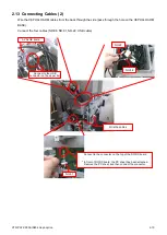
Page 137: ...hole on the CEPHALO ARM BASE Connect the four cables NO 86 NO 91 NO 22 USB cable NO 22 NO 86 A VALUE board Connect to the USB connector on the upper tier Connect to the connector on the top of the DC...

Page 138: ...006 IN004 Ceph option 2 11 2 14 Fixing Cables Fix the cables of CEPHALO ARM with the NYLON CLIP NK 6N x1 Screw bag I and PN3X10 P3 CM1 x1 Screw bag I on the CEPHALO ARM BASE NYLON CLIP NK 6N x1 PN3X10...

Page 139: ...t the CEPHALO ARM while turning the adjustment screw 1 ULTRA LOW HEAD CP5X10 BK Screw bag G so that the level display turns to 0 0 0 1 4 The same as step 2 set up another level at Level setup place 2...

Page 140: ...and Firmware 3 1 Checking Ear Rod Ring Sensor 1 Power on the scanner 2 Press and hold the LCD button 3 Enter the password and press the Confirm button 4 Position the EAR RODs and the nose support as...

Page 141: ...ick the START button and check that CEPH_0 is OFF 6 Looking down from above rotate the EAR RODs counterclockwise at 90 intervals 90 rotation position CEPH_90 is OFF 180 rotation position CEPH_180 is O...

Page 142: ...1 0 37 0 1 0 133 2 CT FPGA 1 0 0 1 1 0 0 1 CT FPDC 1 0 1 0 1 0 1 1 Ceph FPGA 1 0 0 2 1 0 0 2 Ceph FPDC 1 0 0 3 1 0 0 3 In Ceph unit there are two firmwares Ceph FPGA and Ceph FPDC According to the oth...

Page 143: ...memory device to Ramdisk area Open 192 168 5 6 ramdisk with using Explorer copy Ceph firmwares to Ramdisk area 2 Upgrade the firmware with using Maintenance mode Click CEPH FX3 button Wait 1 minute Th...

Page 144: ...nt is unnecessary Check that the ring and the pin are in the same height zones Horizontal Radiation field Adjust the angle of X ray irradiation beam Adjust the positions of the right and right edges o...

Page 145: ...the Vertical Ear rod 1 Position the EAR RODs and the nose support as shown on the right 2 Start up the Console software and click System setting button 3 The System Settings screen appears Select the...

Page 146: ...and click Confirm 5 Select the Cephalo tab and click START in the Scanning field The scanner initialization starts 6 The scanner initialization is complete and wait for the status indicator changing t...

Page 147: ...not required Adjustment is not required when the pin black dot is in the center of the ring circular ring Click Cancel and proceed to 4 3 When adjustment is required Adjustment is required when the p...

Page 148: ...halometric sensor unit tilt according to the displayed adjustment value 12 CEPHALO ARM Tilt Adjustment Loosen the fixing screws SCBST8 22 x3 of CEPHALO ARM BASE and rotate the adjustment screw CP8X30...

Page 149: ...ep 9 Supplementary information The X ray beam emitted from the focal point of the X ray tube passes through the apexes of the two Ear rods and reaches the cephalometric FPD If the left and right ear r...

Page 150: ...ncel and proceed to 4 4 When there is a dark area Adjustment is necessary Perform the following procedure I Adjust the yellow frame so that only the bright area is surrounded II Click OK to close the...

Page 151: ...creen on horizontal direction and surround a bright area not include a border by the yellow frame on vertical direction When there is no dark area Adjustment is unnecessary Click Cancel and proceed to...

Page 152: ...djustment direction is UP 1 Just loosen the adjustment screw on the right side enough to make the adjustment 2 Just tighten the adjustment screw on the left side enough to make the adjustment When adj...

Page 153: ...ontal position of the Ear rod ring appears 2 Check positions of the pin black dot and the ring circular ring When the pin is in the ring Adjustment is unnecessary Click Cancel and proceed to 4 6 When...

Page 154: ...ward click OK 4 Check the Result field and adjust the horizontal position of Ear rod ring based on the displayed adjustment value 5 Adjust the horizontal position of Ear rod ring Loosen the fixing scr...

Page 155: ...ization is complete and wait for the status indicator changing to green Exposure instructions are displayed on the screen 8 Press the exposure switch and irradiate X ray beam 9 Perform from step 1 thr...

Page 156: ...XTR PX2 C0006 IN004 Ceph option 4 17 4 6 Dark Air Scan 1 Life the nose support and move the EAR ROD 90 to the PA front Then extend the EAR RODs to full 2 Click Acquire Dark Air frame...

Page 157: ...ion is complete and wait for the status indicator changing to green Exposure instructions are displayed on the screen 4 Press the exposure switch and irradiate X ray beam 5 A message indicates that th...

Page 158: ...n a screen to rotate the EAR ROD to the LA side click OK Please rotate the ear rods to LA position and press OK button Fold the nose support to the sheltered position 8 The scanner initialization is c...

Page 159: ...XTR PX2 C0006 IN004 Ceph option 4 20 9 Press the exposure switch and irradiate X ray beam 10 Select Common tab and click Normal All Func 11 Check that OK has been displayed in Cephalo Dark...

Page 160: ...IN004 Ceph option 5 1 5 Attaching Covers 5 1 Attaching CEPHALO TOP COVER Attach the CEPHALO TOP COVER and secure it with the TR4X10 CM1 x4 Screw bag D TR4X10 CM1 TR4X10 CM1 TR4X10 CM1 TR4X10 CM1 CEPH...

Page 161: ...ich were removed when attaching the Cephalometric sensor unit FIXED COVER RU FIXED COVER RL FIXED COVER RR CHINREST COVER BOTTOM Handgrip 5 3 Attaching CEPHALO CABLE COVER Attach the CEPHALO CABLE COV...

Page 162: ...function of HASP key and check that LA scan and PA scan can be performed Check that the EAR RODs are shown without using phantom Confirm that there is no black area on the radiation field 6 2 Perform...

Page 163: ...2 CM1 2KML00027 4 Nose Support FOREHEAD BASE C PN3X6 P3 CM1 2KML00028 3 UNDER COVER D TR4X10 CM1 2KML00052 4 TOP COVER 5 BOTTOM COVER E CP5X12 I3 CM1 2KML00015 2 CEPHALO CABLE COVER 2 CEPHALO FPD F CP...

Page 164: ...names 7 2 Cable Ties Proved with the Product Parts Name Parts Number Qty Remarks INSULOCK AB190 2KML00161 1 190 mm 7 3 Jig and tool list Screw for adjusting the position of collimator Pull screw M3 x...

Page 165: ...e Pillar there is a short pin for door interlock connection Remove the short pin connector and connect the PA connector of 15m cable assy here 2 2 magnet Fasten the magnet on the sliding door moving d...

Page 166: ...distance 3 2 when the door is made of steel When the customer uses metallic door in the x ray room the effective range will be decreased because the magnetic field is affected by the steel door Theref...

Page 167: ...rocedure when we don t use STAND Apr 28th 2017 Preparation thin metal plate 30 mm x 30 mm thickness 0 4 mm four pieces maximum Spacer plate Procedure Step1 Tentatively fasten the floor screws 4 pieces...

Page 168: ...he floor screws and wall fixture screws Place level measuring tool on the top of Pillar unit shown with red color on the left figure Confirm the horizontal levelness is in 0 1 degree X direction Y dir...

Page 169: ...ce compatibility and service procedure are changed base plate of Pillar unit Stand The new type Pillar unit the Scanner unit must be used with the new type Stand When we install the new type Scanner u...

Page 170: ...bottom plate Caution When we don t replace the bottom plate we will have problems such as we cannot put the metal bottom cover on the Pillar unit or inside cable can be seen from outside Base STD Y415...

Page 171: ...r limit PI Lower limit 35 36 46 46 47 52 52 58 57 58 CN Cephalo Photo INI 0 Cephalo Photo INI 90 Cephalo Photo INI 180 Cephalo Photo INI 270 CN PI 0 degree PI 90 degree PI 180 degree PI 270 degree CN...

Reviews: