background image

..\Manuals\RCI-200-RF150 rev.B.doc 

                                                                                                          Page 15 of 15 

Cable & Antenna Selection & Installation:


The antenna is a very important component in a radio system.  Make sure you consult the factory for 
proper  antenna  selection  for  your  project.    Cable  leading  from  the  radio  to  the  antenna  is  just  as 
important  in  establishing  a  reliable  link.    Special  low-loss  cable  is  available  to  ensure  minimal  signal 
losses  in  the  cable  leading  to  the  antenna.    This  cable  must  be  kept  as  short  as  possible.    We 
recommend  purchasing  the  cable  from  Pribusin  Inc.  to  ensure  a  good  match  for  the  entire  system.  

Regular TV coaxial cable or even satellite dish coaxial cable will not work.


Even ‘good’ TV cables 

have enormous losses at the high frequency of this radio. 
 
Line-of-Sight Installation: 
 
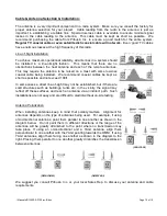
To achieve maximum operational reliability, all antennas in a system should 
be  installed  in  a  line-of-sight  fashion.    This  means  that  there  are  no 
obstructions  between  the  host  antenna  and  each  of  the  remote  antennas.  
This  may  require  the  antenna  to  be  raised  on  a  mast  with  some  low-loss 
coaxial  cable  being  installed.    We  recommend  coaxial  cables  be  kept  as 
short as possible and not exceed 100ft. 
 
In some cases a direct line-of-sight may not be established, but if there are 
solid structures such as buildings, tanks etc. in the vicinity, the signal may 
reflect off these surfaces and reach an antenna via an indirect path.  Such 
installations are not easy and are difficult to predict without on-site testing. 
 
 
Antenna Polarization: 
 
When  installing  antennas  keep  in  mind  that  polarity  matters.    Alignment  for 
antennas depends on the type of antennas being used.  For example, if using 
omni-directional antennas, point  them parallel to one another as shown in the 
diagram  below.    Do  not  point  them  in  different  directions  or  the  range  of  the 
antennas  will  be  greatly  diminished  to  the  point  where  no  transmission  may 
take  place.  If  using  an  omni-directional  and  a  YAGI  antenna,  align  them 
perpendicular to one another with the YAGI pointing towards the OMNI. If using 
YAGI antennas, align them facing one another as shown in the diagram to the 
right. Placing them parallel to one another greatly diminishes the transmission 
between antennas.  


(YAGI-YAGI) 


         (OMNI-OMNI)  


                           (OMNI-YAGI)  

 
We  suggest  you  consult  Pribusin  Inc.  or  your  local  Sales  Rep.  to  discuss  your  antenna  and  cable 
requirements. 

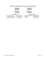
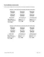
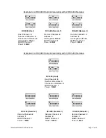
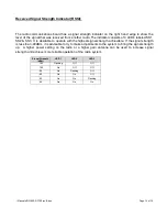
Summary of Contents for RCI-200-RF150

Page 1: ...0 XXX If special or required 24 VDC 2 Dry Contacts and 2 Analog Inputs Input Remote Control Signal Interface XXX SER RS 232 485 Output 2 Form C Contacts and 2 Analog Outputs 117VAC 50 60Hz XXX RF9 900...

Page 2: ...ducts or all non standard products may not be returned for restocking Pribusin Inc warrants equipment of its own manufacture to be free from defects in material and workmanship under normal conditions...

Page 3: ...tion using License free 150MHz Radio Band 2 Watt selectable Radio Power Provides Reliable Communication 2 Dry Contact and 2 Analog Inputs 2 C Relay Contacts and 2 Analog Outputs Point to Point or Host...

Page 4: ...te 1 2 Analog 2 Contact 2 Analog 2 Contact Remote 2 Remote 3 Master to Multi Remote 2 Analog 2 Contact 2 Analog 2 Contact 2 Analog 2 Contact 2 Analog 2 Contact 12 25 10 25 6 5 www pribusin com info pr...

Page 5: ......

Page 6: ......

Page 7: ...a 125mA SLOBLO fuse It can be wired for 240VAC operation by removing de soldering power jumpers J1 J2 and installing soldering jumper J3 When changing the RCI 200 to 240VAC power make sure to change...

Page 8: ...g inputs are connected to the RCI 800 in two fashions 1 Normal 3 wire connection or 2 two wire connection On a 3 wire connected input an external power supply or the 24V power output terminal of the R...

Page 9: ...or from the inputs Care must be taken when connecting the outputs to different devices so that no inadvertent ground loops are established Output Calibration Input Testing The outputs on the RCI 200...

Page 10: ...communications failure occurs If H1 3 IN then analog output 1 will ramp to the setting of K1 and analog output 2 will ramp to the setting of K2 Both outputs will change at a rate determined by the se...

Page 11: ...may distinguish between them There may at most be as many remotes as there are inputs outputs on the host For example an RCI 200 having two analog contact inputs and outputs may communicate with up t...

Page 12: ...2 3 4 They are set as shown in the table SW2 5 SW2 6 Network ID OFF OFF 1 ON OFF 2 OFF ON 3 ON ON 4 SW2 HOST REMOTE 1 of Channels on each Remote of Channels on this Remote 2 of Channels on each Remote...

Page 13: ...quate for most applications If a longer timeout is required it may be set to 10 seconds SW1 6 Reply Timeout sec OFF 1 ON 10 RF Test Mode If the RF Test Mode is enabled the radio will send out a contin...

Page 14: ...s of the host using SW2 3 4 An RCI 200 can at most have 2 channels This is the number of channels that will be exchanged between the host and each remote SW2 3 SW2 4 Channels on Host OFF OFF 1 ON OFF...

Page 15: ...in a system must have a unique address SW1 1 SW1 2 SW1 3 Remote Address OFF OFF OFF 1 ON OFF OFF 2 OFF ON OFF 3 ON ON OFF 4 OFF OFF ON 5 ON OFF ON 6 OFF ON ON 7 ON ON ON 8 Next set the number of chan...

Page 16: ...hannels 1 Interval 10 sec Remote Channels 1 Interval 10 sec Number of Remotes 1 MURS Channel 1 Address 1 MURS Channel 1 Channels on Remotes 1 Power 1 Watt Power 1 Watt RCI 200 Host RCI 200 Remote Host...

Page 17: ...RCI 800 Host communicating with an RCI 800 Remote RCI 800 Host RCI 800 Remote Host Channels 8 Interval 10 sec Remote Channels 8 Interval 10 sec Number of Remotes 1 MURS Channel 1 Address 1 MURS Chann...

Page 18: ...RCI 200 Host RCI 100 Remote 1 RCI 100 Remote 2 Host Channels 2 Number of Remotes 2 Channels on Remotes 1 MURS Channel 1 Power 1 Watt Remote Channels 1 Address 1 MURS Channel 1 Power 1 Watt Remote Cha...

Page 19: ...MURS Channel 1 Power 2 Watt Remote Channels 4 Address 1 Interrogation 30 sec MURS Channel 1 Power 2 Watt Remote Channels 4 Address 2 Interrogation 30 sec MURS Channel 1 Power 2 Watt RCI 800 Host Host...

Page 20: ...It is desirable to operate with the highest signal strength achievable If the signal strength is less than 90dBm it is advisable to try to make adjustments to the system to bring the signal strength...

Page 21: ...ng installed We recommend coaxial cables be kept as short as possible and not exceed 100ft In some cases a direct line of sight may not be established but if there are solid structures such as buildin...

Reviews: