..\Manuals\RCI-200-RF9 rev.B.doc
Page 1 of 15
RCI-200 Connections:
The RCI-200 is the main board of an RCI-200-XXX Telemetry system. It provides the input and output
signal connections as well as the power supply for the unit. A separate communications board is
added to the RCI-200 to allow it to communicate with other units. This communications board may
have its own configuration that is in a separate section of this manual. The following configuration
applies only to the RCI-200 board and is common to all communications interfaces.
AC Power & Fuse:
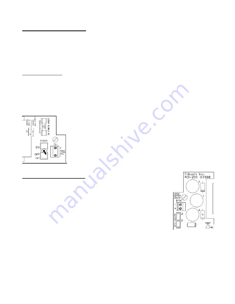
The RCI-200 is typically powered from 120VAC and protected by a 125mA SLOBLO fuse. It can be
wired for 240VAC operation by removing (de-soldering) power jumpers J1 & J2 and installing
(soldering) jumper J3.
When changing the RCI-200 to 240VAC power make sure to change the fuse to half of its value, 80mA.
This is important since at 240VAC the RCI-200 requires only half the current as if it were powered from
120VAC. Proper protection is only achieved by reducing the fuse value as mentioned above.
DC Power & Battery Backup:
The RCI-200 may also be powered from a 24VDC source which could be a
battery or a DC power supply. The 24VDC power input is polarity protected
with a fuse to prevent damage to the RCI-200 by inadvertent reverse polarity.
A DC fuse provision is also provided if this power option is utilized. Insert a
5A automotive type blade fuse into the Battery Fuse socket.


