background image

Fan Powered Variable Volume Terminal uniTs 

17

priceindustries.com   |   FAn Powered VArIAbLe VoLume TermInAL unITs  - manual

MAINTENANCE

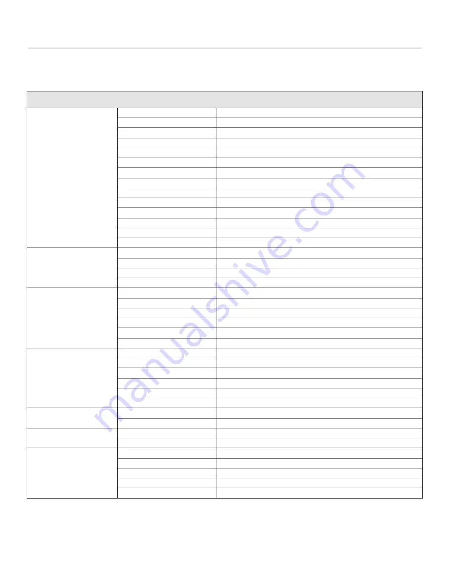
replacement Parts

Component

Part#

Description

PSC Fan Motors

019 150-001

115V - 1/8 HP (Size 20)

019 152-001

115V - 1/4 HP (Size 30)

019 154-003

115V - 1/2 HP (Size 40) (Q2 size 10,12, 14)

019 156-002

115V - 3/4 HP (Size 50 & 70)

019 588-001

208-240V 1/8 HP (Size 20)

019 589-001

208-240V - 1/4 HP (Size 30)

019 590-001

208-240V - 1/2 HP (Size 40)

019 591-001

208-240V - 3/4 HP (Size 50 & 70)

019 592-001

208-240V - 1 HP (Size 60)

019 151-001

277V - 1/8 HP (Size 20)

019 153-001

277V - 1/4 HP (Size 30)

019 155-003

277V - 1/2 HP (Size 40) (Q2 size 10,12, 14)

019 157-003

277V - 3/4 HP (Size 50 & 70)

019 167-001

277V - 1 HP (Size 60)

PSC Fan Speed 
Controllers

233 563-100

8A / 115V (Size 20, 30)

233 563-400

15A / 115V (Size 40, 50, 70) & (Q2 Size 10, 12, 14)

233 563-200

8A / 208/240/277V (Size 20-70) (Q2 Size 10, 12, 14)

233 563-500

10A / 240/277V  (Size 60)

ECM Motors

019 173-001

115/240V - 1/3 HP (Size 10, 20)

019 173-002

277V - 1/3HP (Size 10, 20)

019 171-001

115/240V - 1/2 HP (Size 30, 40, 40, 60)

019 172-001

115/240V - 1 HP (Size 50, 60, Q2)

019 171-002

277V - 1/2 HP (Size 30, 40)

019 172-002

277V - 1HP (Size 50, 60, Q2)

EON Fan Motors

019 178-002

120/240V - 1/3 HP (Size 20)

019 179-002

277V - 1/3HP (Size 20)

019 178-001

120/240V - 1/2 HP (Size 30, 40)

019 179-001

277V - 1/2 HP (Size 30, 40)

019 178-004

120V/240V - 1 HP (Size 50, 60)

019 179-004

277V - 1HP (Size 50, 60)

ECM Speed Controller

232 953-100

ECM Standard Fan Speed Controller

232-953-200

ECM Deluxe Fan Speed Controller

Disconnect Switch

019 903-001

115/277V - 15A

019 903-003

208/240V - 30A

Capacitors

019 874-001

5 mfd

019 874-006

7.5 mfd

019 874-002

10 mfd

019 874-003

15 mfd

019 874-007

20 mfd

Summary of Contents for FDV Series

Page 1: ...Revision 01 Issue Date 03 17 17 2014 Price Industries Limited All rights reserved MANUAL INSTALLATION Fan Powered Variable Volume Terminal Units FPV FEV FDV Series...

Page 2: ...dure 6 ECM Motor Adjustment 6 ECM Speed Controller Deluxe Standard 7 Fan Performance Curves FPV FEV FDV PSC Motor 8 Fan Performance Curves ECM Motor 9 Pneumatic Calibration Procedures CP100 CP200 12 C...

Page 3: ...efer to the submittal drawing for illustration Caution To Contractors 1 Fan powered terminal units are not intended for use as temporary heat or ventilation sources during building construction The te...

Page 4: ...per action application and controller set points Options accessories and appropriate control diagrams are also identified If field adjustment of the controller set points should become necessary follo...

Page 5: ...oval 4 Do not install tight to slab avoid contact with other obstacles such as rigid conduit and sprinkler piping This can cause excessive vibration and noise transmission 5 Install the unit in a loca...

Page 6: ...field wire size 3 Check voltage requirements prior to power supply connection Refer to the electrical label located near the electrical control box and also refer to the schematic drawing provided on...

Page 7: ...i Turn power on to the terminal unit iv Restore damper to normal position The above procedure will prevent backward rotation of the fan motor on start up 7 If field amperage draw readings of the fan m...

Page 8: ...eam duct static pressure is a minimum 0 1 W G 0 2 W G required for units with electric heater for stable control operations 9 The primary air volume both minimum and maximum set points are factory cal...

Page 9: ...des 1 Speed Adjustment is easier and more precise with the digital display and push buttons than with a standard dial 2 Motor RPM displays the real time motor speed to aid in troubleshooting 3 BAS inp...

Page 10: ...20 30 40 50 60 70 80 200 300 400 500 600 700 800 1800 10 20 30 40 50 60 70 80 2000 2200 2400 2600 2800 3000 3200 200 10 20 30 40 50 60 70 80 400 600 800 1000 1200 1400 1600 1200 1000 10 10 20 30 40 5...

Page 11: ...or For terminal units with electric reheat a minimum discharge static of 0 2 w g is recommended for stable operation of heater controls UNIT SIZE 10 NO COIL 1 2 ROW COIL UNIT SIZE 30 NO COIL UNIT SIZE...

Page 12: ...20 0 10 0 200 400 600 800 1000 1200 1400 1800 1600 0 70 0 60 0 50 0 40 0 30 0 20 0 10 0 200 400 600 800 1000 1200 1400 1600 0 70 0 60 0 50 0 40 0 30 0 20 0 10 0 250 500 750 1000 1250 1500 1750 2000 0...

Page 13: ...on this page UNIT SIZE 60 NO COIL UNIT SIZE 60 2 ROW COIL UNIT SIZE 60 1 ROW COIL ECM Motor Data Unit Size Motor H P Full Load Amps 115V 240V 277V 20 1 3 3 9 1 9 1 6 30 1 2 7 0 3 5 3 0 40 1 2 7 2 3 8...

Page 14: ...vel in response to the adjustments Verify the minimum set point by cycling the thermostat pressures 4 Apply 15 psi minimum air pressure to the thermostat connection at the controller 5 Turn the maximu...

Page 15: ...pressure not end span pressure v Replace gauge tap cap 4 Air Volume Limits i Remove the caps from the tees in the HI red and LO green tubes leading from the air flow sensor in the assembly inlet Conn...

Page 16: ...il the gauge reads the required differential pressure for minimum air volume Turn the dial slowly allowing time for the damper actuator to complete its travel in response to the adjustment 7 Cycle the...

Page 17: ...on the principle of mass flow rather than pressure differential Controls utilizing a dead ended pressure transducer will allow field measurement with the gauge taps and calibration curves provided 2 S...

Page 18: ...metal or flexible It is to be the same size as the inlet between the unit inlet and any transition take offs or fittings Poor inlet conditions may necessitate controller re calibration 6 Check the flo...

Page 19: ...233 563 100 8A 115V Size 20 30 233 563 400 15A 115V Size 40 50 70 Q2 Size 10 12 14 233 563 200 8A 208 240 277V Size 20 70 Q2 Size 10 12 14 233 563 500 10A 240 277V Size 60 ECM Motors 019 173 001 115 2...

Page 20: ...controls information please reference PIC PAC manual 076 730 002 Pneumatic CP100 Controller 076 824 001 Pneumatic CP200 Controller 076 823 001 Pneumatic CP101 Controller Actuators For actuators infor...

Page 21: ...00 Sizes 20 and 30 with high capacity water coils 042314 015 17 500 24 500 Size 40 bare unit 042314 015 15 500 24 500 Size 40 with water coil 042314 013 19 500 24 500 Size 40 with high capacity water...

Page 22: ...Fan Powered Variable Volume Terminal Units 20 Fan Powered Variable Volume Terminal Units Manual priceindustries com NOTES...

Page 23: ...Fan Powered Variable Volume Terminal Units 21 priceindustries com Fan Powered Variable Volume Terminal Units Manual NOTES...

Page 24: ...s document contains the most current product information as of this printing For the most up to date product information please go to priceindustries com 2014 Price Industries Limited All rights reser...

Reviews: