background image

14

Center-Mount Articulating Foot Platform

The center-mount articulating foot platform maintains the 
correct knee-to-heel measurements when the user’s legs are 
being elevated. 

See figure 15.

 The center-mount articulating 

foot platform elevates to 170°, has standard calf pads that are 
depth and height adjustable (

see figure 17

), has a maximum 

weight capacity of 450 lbs. (204 kg), and has an operating 
temperature of 40°F (4°C) to 105°F (40°C). It is available 
with all TRU-Balance Power Positioning Systems and with 
the Synergy Seating System. The articulating foot platform 
operates through the power chair controller or toggle switch.

NOTE: Operation instructions using the joystick 4-way 
toggles are discussed below. If you are using a different 
toggle, the Attendant Control Module, or a different 
operating device, please refer to the operation manual 
supplied with that device and/or your power chair 
owner’s manual.

To operate the center-mount articulating foot platform:

1.  Push the toggle switch to the right to elevate the center-

mount articulating foot platform.

2.  Push the toggle switch to the right, release, then push 

to the right again to lower the center-mount articulating 
foot platform.

To adjust the angle of each foot plate:

1.  Flip up the foot plate and locate the screw. 

See figure 16.

2.  Turn the screw to raise or lower the front of the foot plate.

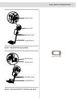
Figure 15. Center-mount Articulating Foot Platform

Swing-away Calf Pads

Several of the front riggings are equipped with swing-away 
calf pads that are height and depth adjustable.

To adjust the swing-away calf pad height:

1.  Remove the height adjustment screws. 

See figure 17.

2.  Adjust the calf pad up or down to the desired height.
3.  Reinstall the height adjustment screws and tighten.

To adjust the swing-away calf pad depth:

1.  Remove the depth adjustment screw. 

See figure 17.

2.  Adjust the calf pad in or out to the desired depth.
3.  Reinstall the depth adjustment screw and tighten.

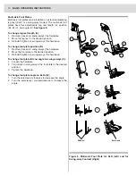
Figure 17. Swing-away Calf Pad Adjustment (ALR Shown)

Height

Adjustment

Screws

Depth

Adjustment

Screw

BASIC OPERATION INSTRUCTIONS

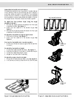
Figure 16. Angle Adjustment for Foot Plate

Setscrews

Summary of Contents for Front Riggings Quantum

Page 1: ...ridemobility co nz UK 32 Wedgwood Road Bicester Oxfordshire OX26 4UL www quantumrehab co uk B V Authorised EU Representative De Zwaan 3 1601 MS Enkhuizen The Netherlands www quantumrehab eu Italy Via...

Page 2: ...s icon is represented as a black symbol with a red circle and red slash Intended Use A wheelchair component is a device intended for medical purposes that is generally sold as an integral part of a wh...

Page 3: ...es where our Power Chairs are sold We have chosen to compose this manual using language and spellings common to the USA Since we recognize that not all English speaking countries use the same words or...

Page 4: ...operation Your safety depends upon you as well as your provider caretaker or healthcare professional in using good judgment This manual is to be used in addition to the power base owner s manual that...

Page 5: ...unity or resistance to EMI The higher the immunity level the greater the protection against EMI This product has been tested and has passed at an immunity level of 20 V m Be aware that cell phones two...

Page 6: ...xis Foot Plate SWING AWAY POWER ARTICULATING LEG RESTS ALR Maintain correct knee to heel measurements when user s legs are raised or lowered Pediatric 60 90 HD ELR ADJUSTABLE CENTER MOUNT FOOT PLATFOR...

Page 7: ...igure 4 2 Adjust the foot plate to the desired position See figure 4 3 Tighten the hardware on the bottom of the foot plate To adjust the SFR angle when equipped with 60 90 SFRs 1 Remove protective fo...

Page 8: ...adjustment screws Figure 5 Swing away 60 90 Leg Rests Figure 6 Heavy Duty Drop in Leg Rests Elevating Leg Rests Elevating Leg Rests ELRs offer an infinite range of adjustment for the leg angle To rota...

Page 9: ...Leg Rests Figure 8 International Style 14 Elevating Leg Rests Release Lever A Release Lever B Adjustment Screws Leg Rest Extension Release Lever A Release Lever B Adjustment Screws Leg Rest Extension...

Page 10: ...foot plate position B 1 Remove loosen on swing aways the hardware 2 Move the foot plate to the desired position 3 Reinstall tighten on swing aways the hardware To change foot plate tilt and angle on s...

Page 11: ...and tighten To adjust the foot platform angle using the lever 1 Pull down on the lever See figure 11 2 Adjust the foot platform to the desired angle See figure 11 To return the foot platform to a neu...

Page 12: ...ir controller or toggle switch NOTE Operation instructions using the joystick 4 way toggles are discussed below If you are using a different toggle the Attendant Control Module or a different operatin...

Page 13: ...n manual supplied with that device and or your power chair owner s manual To operate the combined leg rests 1 Push the toggle switch to the right to elevate both leg rests 2 Push the toggle switch to...

Page 14: ...t platform 1 Push the toggle switch to the right to elevate the center mount articulating foot platform 2 Push the toggle switch to the right release then push to the right again to lower the center m...

Page 15: ...s icon is represented as a black symbol with a red circle and red slash Intended Use A wheelchair component is a device intended for medical purposes that is generally sold as an integral part of a wh...

Page 16: ...ridemobility co nz UK 32 Wedgwood Road Bicester Oxfordshire OX26 4UL www quantumrehab co uk B V Authorised EU Representative De Zwaan 3 1601 MS Enkhuizen The Netherlands www quantumrehab eu Italy Via...

Reviews: