background image

28

www.pridemobility.com

Quantum Q6 Edge

V .   C O M F O R T   A D J U S T M E N T S

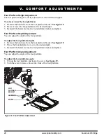
Foot Platform Height Adjustment

The foot platform height is easily adjusted to several different heights.

To raise or lower the foot platform:

1. Remove the hardware from the foot platform bracket. 

See figure 19.

2. Raise or lower the foot platform to the desired height.

3. Reinstall the hardware into the foot platform bracket and tighten.

Foot Platform Depth Adjustment

You can adjust the depth of the foot platform.

To adjust the foot platform depth:

1. Remove the hardware from the foot platform bracket. 

See figure 19.

2. Move the foot platform in or out to the desired depth.

3. Reinstall the hardware into the foot platform bracket and tighten.

Foot Platform Angle Adjustment

You can adjust the angle of the foot platform.

To adjust the foot platform angle:

1. Flip up the foot platform and locate the screw. 

See figure 19.

2. Turn the screw to raise or lower the front of the foot platform.

Figure 19. Foot Platform Adjustment

FOOT 

PLATFORM 

BRACKET

SCREW

HARDWARE

Summary of Contents for Quantum Q6 Edge HD

Page 1: ...QUANTUM Q6 Edge...

Page 2: ...SA The symbols below are used throughout this owner s manual and on the power chair to identify warnings and important information It is very important for you to read them and understand them complet...

Page 3: ...Edge www pridemobility com 3 I INTRODUCTION 4 II SAFETY 5 III YOUR POWER CHAIR 17 IV ASSEMBLY 21 V COMFORT ADJUSTMENTS 24 VI BATTERIES AND CHARGING 31 VII CARE AND MAINTENANCE 35 VIII WARRANTY 41 C O...

Page 4: ...including voiding the warranty PURCHASER S AGREEMENT By accepting delivery of this product you promise that you will not change alter or modify this product or remove or render inoperable or unsafe a...

Page 5: ...n drive tyres Maximum seating weight Do not allow unsupervised children to play near the power chair while the batteries are charging Read and follow the information in the owner s manual I I S A F E...

Page 6: ...converter or the battery charger Keep tools and other metal objects away from battery terminals Contact with tools can cause electric shock Use only AGM or Gel Cell batteries to reduce the risk of le...

Page 7: ...t Negative Black Terminal Post Connect Red wires to Red Positive Terminal Posts Connect Black wires to Black Negative Terminal Posts EMI RFI This product has been tested and passed at an immunity leve...

Page 8: ...nd recycling Contact your Quantum Rehab Provider for information on proper disposal and recycling of your Pride product and its packaging I I S A F E T Y Class II Equipment Manufactured in Power chair...

Page 9: ...practice Simply take your time and you will soon be in full and confident control as you maneuver through doorways on and off of lifts up and down ramps and over moderate terrain Below are some precau...

Page 10: ...89476 Incline Information More and more buildings have ramps with specified degrees of inclination designed for easy and safe access Some ramps may have turning switchbacks 180 degree turns that requ...

Page 11: ...mited to corner ing speed steering angle how sharply you are turning uneven road surfaces inclined road surfaces riding from an area of low traction to an area of high traction such as passing from a...

Page 12: ...r before storing charging or operating your power chair PROHIBITED Operating in rain snow salt mist spray conditions and on icy slippery surfaces can have an adverse effect on the electrical system Ma...

Page 13: ...care that handbags packages or power chair accessories do not become caught in lift doors Lift Systems Elevation Products If you will be transporting your power chair during travel you may find it ne...

Page 14: ...into seats approved by the vehicle manufacturer Batteries In addition to following the warnings below be sure to comply with all other battery handling information For more information about your powe...

Page 15: ...in the presence of a qualified healthcare professional WARNING Do not bend lean or reach for objects if you have to pick them up from the floor by reaching down between your knees or if you have to re...

Page 16: ...items may reduce the resistance to flammability of the fabric Electromagnetic and Radio Frequency Interference EMI RFI WARNING Laboratory tests have shown that electromagnetic and radio frequency wav...

Page 17: ...he armrests seatback and seat base The power base assembly includes two motor brake assemblies two drive wheels four caster wheels two batteries and wiring harnesses See figures 5 6 and 7 Figure 5 The...

Page 18: ...nd the motors batteries and the battery charger is pro vided by one or more wiring harnesses See figure 7 Controller Harness Connector The controller harness connector is where the controller plugs in...

Page 19: ...s and the electronics If the circuit trips allow your power chair to rest for approximately one minute Next push in the circuit breaker button turn on the controller and con tinue normal operation Tur...

Page 20: ...oth manual freewheel levers for drive mode drive motor engaged See figure 9 NOTE You must turn off the power before disengaging the drive motors otherwise you may get an error code on the controller T...

Page 21: ...r making comfort adjustments NOTE Any nylon insert lock nut removed during the disassembly or adjustment of the power chair must be replaced with a new nut Nylon insert lock nuts should not be reused...

Page 22: ...and you may lose control of the seat if they do so To install the seat 1 Tilt the seat back and slide the rear extrusion onto the rear trapeze bar See figure 11 2 Lower the front extrusion onto the f...

Page 23: ...ng seat option While the seat itself may be any one of the styles offered for this model the way the seat base attaches to the power base is different To install the power elevating seat l Place the s...

Page 24: ...e to lift or carry them Please refer to the specifications table for specific component weights before you disassemble the power chair WARNING Remove the occupant from the power chair before making an...

Page 25: ...from the power base 5 Remove both extrusions from the bottom of the seat 6 Reposition the extrusions on a different set of mounting holes You must move both extrusions the same number of holes either...

Page 26: ...mrest knobs on each side of the armrest receiver bracket See figure 17 2 Loosen the knobs 3 Slide the armrests in or out to the desired width 4 Tighten the knobs Armrest Angle Adjustment To change the...

Page 27: ...the controller position 1 Turn off the power to the controller 2 Unplug the controller connector s from the power base 3 Remove any wire ties securing the controller har ness to the armrest 4 Flip up...

Page 28: ...oot Platform Depth Adjustment You can adjust the depth of the foot platform To adjust the foot platform depth 1 Remove the hardware from the foot platform bracket See figure 19 2 Move the foot platfor...

Page 29: ...ehab Provider WARNING The power elevating seat option is intended for use on a level surface only Never raise the seat from its lowest position on an inclined surface Failure to heed this warning can...

Page 30: ...seat base for each side of the power chair seat 3 Tighten both screws To adjust the positioning belt for operator comfort 1 Once seated insert the metal tab on one side of the belt into the plastic h...

Page 31: ...charger directly into a properly wired standard electrical outlet PROHIBITED Do not allow unsupervised children to play near the power chair while the batteries are charging Pride recommends that you...

Page 32: ...is how the charger maintains a charge but does not overcharge the battery Can I use a different battery charger You should use the charger supplied with the power chair It is the safest most efficien...

Page 33: ...that are similar in performance Refer to the specifications table for more information regarding the batteries used with your power chair WARNING Corrosive chemicals contained in batteries Use only A...

Page 34: ...r power chair for an extended period fully charge the batteries prior to storage Disconnect the battery harnesses and store the power chair in a warm dry environment Avoid temperature extremes such as...

Page 35: ...ntly exposed to sources of water such as incontinence should be inspected often for corrosion and electronic components may need to be replaced frequently Temperature Some of the parts of your power c...

Page 36: ...spect the controller from the power base Look for corrosion Contact your Quantum Rehab Provider if necessary Ensure that all parts of the controller system are securely fastened to your power chair Do...

Page 37: ...neoprene silicone and polyurethane materials Cleaning and Disinfection Use a damp cloth and mild non abrasive cleanser to clean the plastic and metal parts of your power chair Avoid using products th...

Page 38: ...he blocks Battery Replacement A battery wiring diagram is printed on a decal located on the front cover See the specification table for correct battery specifications MANDATORY Battery posts terminals...

Page 39: ...et up and away from the power base 4 Disconnect the quick release battery connectors See figure 7 5 Remove the batteries 6 Disconnect the battery harness from each battery 7 Connect the battery harnes...

Page 40: ...s Does not power up Powers up but does not move Loose seat or seating components Corrective Maintenance If the battery condition meter does not light up when you turn on the power Check the harness co...

Page 41: ...rantee does not extend to those items which may need replacement due to normal wear and tear tyres belts bulbs upholstery plastic shrouds motor brushes fuses and batteries or damage to the product cau...

Page 42: ...42 www pridemobility com Quantum Q6 Edge N O T E S...

Page 43: ......

Page 44: ...the factory Date Inspected Inspector Inclusion of all Parts Joystick Serial Number Controller Serial Number Left Motor Serial Number Right Motor Serial Number Fit and Finish Performance INFMANU4123 P...

Reviews: