background image


www.pridemobility.com


6


I I .   S A F E T Y


LIFTING CAPABILITIES 

The lift system is designed to lift a maximum weight of 260 lbs. (120 kg) or 440 lbs. (200kg) depending on 
the model purchased. Check this by referring to labels on the lift arm. Under no circumstances should the 
lift system be made to exceed this weight limit. Subjecting the lift system to the strain of lifting more than it 
is  designed  to  may  cause  it  to fail,  resulting  in damage  to the  mobility  product  and/or  injury  to  the lift 
operator. Refer to the mobility product specifications for information on the overall weight of the mobility 
product before lifting with the lift system. 
 

WARNING! Exceeding the maximum lifting capacity of 260lbs or 440lbs may cause the lift 

system to fail, resulting in damage to the mobility product and/or injury to the lift operator. 


MANDATORY! Adding accessories, oversized batteries, or  a  different seat  will  increase the 

weight of your mobility device. Verify with your authorized Pride Provider that the total weight 

of your mobility device, including additions, DOES NOT exceed 260 lbs or 440 lbs. (120/200 kg). 


INSTALLATION 

This hoist is intended for installation in the rear luggage compartment of a vehicle.  Read and fully understand 
the installation instructions provided with the hoist and the related fitting kit instructions before installing the 
lift system. 


WARNING! This hoist is only intended to be installed by an authorized Pride installer or 
qualified technician. Separate installation instructions are provided with the hoist and the 
installation kit.  Read and fully understand both manuals prior to installation. 


LIFTING NON-PRIDE PRODUCTS 

The lift system is an extremely versatile device, which users may employ to lift items other than Pride 
products. Pride has  no  control over  such  use,  nor  can  Pride  anticipate every possible use  to  which a  lift 
system may be put. Operating the lift system outside of the safe limits as discussed in this manual or using the 
lift system to lift any item deemed by Pride to be incompatible with the lift system is done at the operator’s 
own risk, and Pride accepts no liability for damage or injury resulting from such use. 
 

PRE-LIFT INSPECTION 

There should be no sharp edges on the hoist, the fitting kit or the scooter brackets. If you find any sharp 
edges, please contact your supplier before use.  Make sure that you are completely happy with the operation 
of your hoist before operating it yourself. Misuse of the product could result in injury. Inspect the lifting 
straps before every use for twisting, fraying or signs of wear.  If signs of wear become evident, have the 
them replaced by your authorized Pride Provider.


WARNING! A frayed or worn strap can snap, resulting in damage to the mobility product 
and/or injury to the lift operator.  


OPERATOR POSITIONING 

Keep hands clear of the lift arm while the lift system is lifting/lowering or loading in/out a mobility product. 
The operator of the lift should stand a safe distance from the unit being lifted/lowered to ensure that his/her 
feet are never positioned under a raised mobility product. 


Summary of Contents for Zeus 260/440lb

Page 1: ...260 440lb AFFIX BARCODE LABEL HERE...

Page 2: ...hibited action can cause personal injury and or equipment damage On the product this icon is represented as a black symbol with a red circle and red slash Please fill out the following information for...

Page 3: ...www pridemobility com 3 C O N T E N T S I INTRODUCTION 4 II SAFETY 5 III TECHNICAL 8 IV FITTING INSTRUCTIONS 9 V WIRING 13 VI INSTALLING REMOVING 15 VII TROUBLESHOOTING 17 VIII WARRANTY 18...

Page 4: ...GREEMENT By accepting delivery of this product you promise that you will not change alter or modify this product or remove or render inoperableor unsafe any guards shields or other safety features of...

Page 5: ...acity Do not sit on mobility product while operating the lift system or during transport Pinch Crush points created during assembly and or operation Keep hands fingers away from moving components duri...

Page 6: ...or qualified technician Separate installation instructions are provided with the hoist and the installation kit Read and fully understand both manuals prior to installation LIFTING NON PRIDE PRODUCTS...

Page 7: ...er be operated by a child or any person not deemed appropriate to operate the equipment by the technician who installed it WARNING The safety Pin must be fitted into the top pin in the A Frame prior t...

Page 8: ...40lbs 200kg 260lbs 120kg Power supply 12V dc Maximum current draw 22 Amps Product Materials Aluminum and Mild Stainless Steels Material Finish Powder Coated Carbon COMPONENT DESCRIPTION 1 2 3 4 5 6 7...

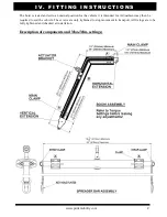
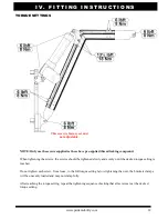
Page 9: ...d set to a nominal position for the vehicle it is intended for Adjustment may then be required to suit the vehicle The screws are only tightened to stop movement in transport All fixings are to be ful...

Page 10: ...checked Do not load the hoist at this stage 10 Once satisfied that the hoist moves through its intended movements without fouling the boot opening tighten the main clamps and the actuator brackets to...

Page 11: ...ket positions and the reference used in the actuator setting chart A B C D E F DO NOT USE The following table shows the lower actuator bracket positions recommended for various actuators and loads Mod...

Page 12: ...ould be tightened slowly and evenly until the desired torque setting is reached Do not tighten each screw from loose to the full torque setting before tightening the next the brackets clamps will be u...

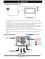
Page 13: ...e holder provided on the positive connection Wire as follows BLACK negative RED positive A spare 25 AMP fuse is provided and should be handed to the customer or located in an obvious and appropriate p...

Page 14: ...www pridemobility com 14 V W I R I N G CONNECTING ACTUATORS Test operation with handset If the movement is opposite to expected then reverse the polarity of the connector s REVERSING POLARITY...

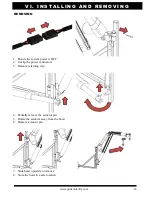
Page 15: ...pper pin before aligning the lower pin The hoist should slide smoothly down into place 2 Half engage actuator pin 3 Rotate the hoist and align with it actuator 4 Fasten together with the actuator pin...

Page 16: ...G REMOVING 1 Ensure the system power is OFF 2 Unclip the power connectors 3 Remove retaining clip 4 Partially remove the actuator pin 5 Rotate the actuator away from the hoist 6 Remove actuator pin 7...

Page 17: ...r caught on the vehicle Is the load of more than the hoist s capacity Please check this weight with your supplier Check the fuse This is next to the car s battery a spare fuse is always supplied The a...

Page 18: ...n as defined by an authorized Pride Provider In the event of damage or defects in the actuator the hoist should be returned to your authorized Pride Provider for evaluation No wires must be cut as the...

Page 19: ...www pridemobility com 19 N O T E S...

Page 20: ...www pridemobility com 20...

Reviews: