fit I system track installation prep
Follow all local and national electrical codes.
For assistance please call Prima Customer Ser
vice at 562-407-3079
A1
A2
IMPORTANT Please read these instructions prior to installation. Refer to the Prima catalog for proper lamp type and maximum wattage for fixtures.
Prima is not responsible for any fixture or system failure caused by unsupported lamps. Contact Prima customer service for the latest updates on
which lamps we support and proper usage. Prima low voltage transformers must be used with all Prima Lighting product installations. All warranties
are void if Prima transformers are not used. Prima’s catalogs provide general information and suggestions for proper dimmer usage. Please consult
our customer service department with any questions regarding dimmer specifics. Prima is not responsible for any damage caused by improper
dimmer specification and usage. Use only qualified electrician for installation. Adhere to all local and national electrical codes prior to installation.
It is strongly recommended that gloves are used when handling the FIT I System track. Oils and dirt from fingers can sometimes permanently
mark the finish. Track should be cleaned with a damp cloth and thoroughly dried before fixture installation.
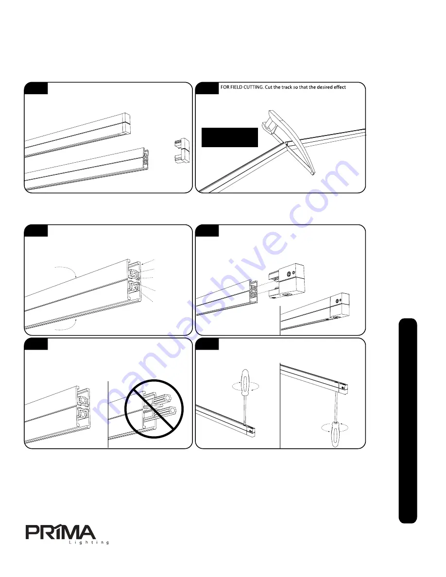
Determine whether the FIT I track length will be installed as
part of a series of connected track lengths or as a single
stand alone track length. Before attempting to field cut the FIT I track,
ensure that the end caps are firmly installed into both ends. If an end
cap has become loose during shippping, replace it.
and lengths can be achieved. FIT track may be field cut with
an ordinary hacksaw. Be sure to use a FINE-TOOTH METAL CUTTING
BLADE. Be sure to deburr and clean all cuts prior to final assembly.
fit I system track connector/powerfeed basics
B1
B2
Connectors are available for extending track length, turning corners or creating intersections in the run. Great care must be taken to ensure
the connector is installed properly.
FIT I track is constructed of an aluminum housing which
doubles as the neutral conductor. Each of the two slots of the
track include one conductor and one insulator. The slots may used as
two separate circuits with the proper use of powerfeeds. The track may
also be configured as one circuit for both slots with the use of a jumper.
When installing a connector or powerfeed, place the opposite
end of the track length against a solid flat surface to keep the
internal parts of the track from sliding. Carefully align the connector pins
on the connector with the holes in the track’s conductors. Insert the
connector all the way into the track until it stops.
Track housing/
Neutral
Conductor 1
Insulator 1
Slot 1
Slot 2
Conductor 2
Insulator 2
B3
B4
When installing a connector at the end of a FIT I track length,
great care should be taken to ensure the connector is properly
installed. After the connector has been inserted into the end of the track,
inspect the opposite end of the track. If the inslulators and conductors
are flush with the end, then the installation was successful. If the
conductors protrude past the end of the track AT ALL then connector is
not properly installed.
When the connector or powerfeed is properly inserted into the
track length, secure the installation by tightenting the lock
screws located at the top and bottom of connector. DO NOT
OVERTIGHTEN THE SCREWS.
Opposite end after a
proper connector installation.
Opposite end after an
improper connector installation.
FIT SYSTEM TRACK
MAY NOT BE BENT IN
ANY WAY
FIT I System track
may not be bent
13615 Marquardt Ave. Santa Fe Springs, CA 90670
Ph. 562-407-3079 . Fx. 562-407-3069
www.primalighting.com
*Caution:
Do not break the insulator inside
the chamber while using the
screw-in function. Broken insulator
will cause short of circuit.
*Caution
REV
.033015
prima fit I system
general installation instructions part 1 of 12


