background image

P r i m a L u c e L a b   i S r l


S p i d e r 2 3 0   u s e r   m a n u a l

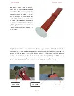
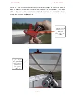
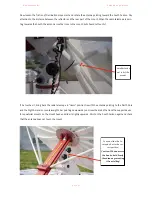
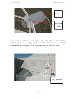
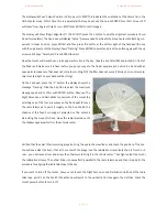
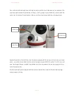
Now take the RAL10PL pier support (

21

) and bring it close to the column. 

You can attach it to the column using two clamps. This support allows you 
to set the receiver box at the base of the column.  

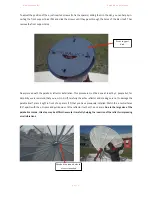
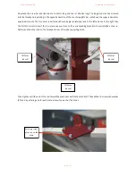
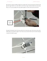
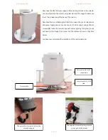
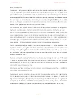
Now take the box containing the RAL10PL


receiver, the control electronics 

and power supply devices. You can secure it to the support using 4 M6x12 
screws (

29

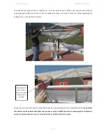
). Place the receiver box with cables passing facing the ground 

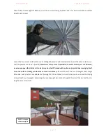
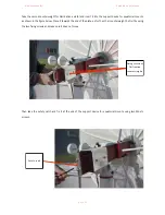
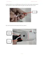
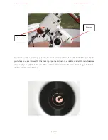
as shown in this image. Then connect all the cables as shown in the photo 
below.  

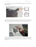
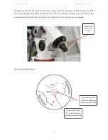
You have now completed the installation of the radio telescope! 

!

!

!

p a g e  

!

2 9

The gray cable is inserted below the 

mount handpad

Power cable

Network cable for PC 

connection

Coaxial cable for LNB 

link

The angular black cable plugs into the 

power jack of the mount

Summary of Contents for SPIDER230

Page 1: ...s instrument is made by PrimaLuceLab iSrl via Roveredo 20 b 33170 Pordenone Italy For any questions con cerning the use support and warranty information please refer to the addresses given in the relevant documents Prima LuceLab i Srl Vi a Roveredo 2 0 B 33170 Pordenone www primalucelab com ...

Page 2: ...ponents such as equatorial mount or receiver Do not open or subject to damage shock or excessive shock any electronic parts For example do not drop the receiver or other elements Do not short circuit the electronic elements Do not expose the instrument to extreme temperatures above 50 C Do not incinerate or dispose in fire any component of the radio telescope Do not wet any electrical or electroni...

Page 3: ...lar alignment and finder alignment 30 First use mount alignment 36 First use antenna setup 38 RAL10PL receiver 41 RadioUniverse control software installation 45 Advanced functions record a transit 50 Advanced functions record a radio picture 53 Advanced functions performances optimization 56 Advanced functions create a radio map with RUviz 60 Experiments the Sun radio waves source 63 p a g e 2 ...

Page 4: ...luded accessories and parts will vary depending on the order p a g e 3 4 quarters of parabola Support device for equatorial mounts Tie rods supporting block 2 5Kg counterweights for Declination axis 1 support plates with 3 holes 3 support plates with 4 holes 4 support rods for feed horn 1169mm long 2 1 4 3 5 8 7 3 rear tie rods 2 1422mm long 1 1453mm long 6 ...

Page 5: ...g e 4 Front support disk 4 spacers LNB with feed horn Collimation rod Equatorial mount head if ordered 2 5Kg counterweights for Right Ascension axis with mount if ordered Pier with mount adapter 10 9 12 11 14 13 16 15 Feed horn support with LNB case ...

Page 6: ...pport disks M12x55 screw with ball bearing 16 M6x50 screws with 2 washers and 1 nut each 8 M6x30 screws with 1 washer and 1 nut each 11 M6x16 screws with 1 washer each 18 17 21 19 23 22 26 24 27 29 Finder support for counterweights shaft M12x20 screw 25 28 4 M6x55 screws RAL10PL receiver with control electronics 20 M6x12 screw with washer ...

Page 7: ...pport device for equatorial mounts Tie rods supporting block 2 5Kg counterweights for Declination axis 5 Support rods for feed horn 6 7 Rear tie rods Support plate with 4 holes 9 Feed horn support with LNB case 12 13 14 15 LNB with feed horn Equatorial mount head 17 Finder support for counterweights shaft 18 8x50 finder 3 2 7 19 Glass Sun filter for finder 30 Right Ascension counterweights shaft P...

Page 8: ...cision alignment since later when the pier will be fixed it will be possible to adjust the mount position with a maximum displace ment of about 15 degrees Unscrew the 4 screws around the pier remove the red adapter and now connect this under the mount as explanations on page 8 and put it all on the column The correct direction is the one shown in the photo at left by the red line cor responding to...

Page 9: ...isks 21 Screw the M16x35 screws 22 that you can tighten to perfectly horizontal adjust the pier with the aid of a bubble photo below right When the pier is leveled secure it by inserting and tightening the 3 nuts on the 3 threaded rods p a g e 8 Support disk M16 screw Threaded rods Nut for threaded rod Threaded rod ...

Page 10: ... move left or right with the provided micrometric azimuth movement when you need to perform a precision polar alignment Then enter the mount head 13 with the installed flange on the pier and secure it with the 4 locking screws pre viously loosened Loosen the locking screw of counterweights bar and pull down the counterweight shaft itself Now you can open the clutches of the two mount movements Rig...

Page 11: ...tension bar you can find in the mount case Insert the two 5Kg white counterweights 14 and then stop at the top of the bar closing their black screws note make sure they are locked and do not move on p a g e 10 2 5Kg counter weights for Right Ascension Clutch for Declination axis Counterweights bar locking screw Counter weights bar Clutch for Right Ascension axis Extension rod for counterweights ba...

Page 12: ...ear in the search box The first number indicates the latitude For example if it appears 45 992952 12 635844 then the latitude is almost 46 degrees Now set the latitude in the mount and adjusts with the adjustment screws The way this is done depends on the type of equatorial mount used if you use the N EQ6 SynScan find the two latitude adjustment screws in the lower part of mount closest to the pie...

Page 13: ... gov geomag WMM data WMM2010 WMM2010_D_MERC pdf To correctly point true north with a compass you have to subtract to 360 the magnetic declination of your place of observation this will be the direction of the North For example in Italy we have a magnetic declination East ie positive by about 2 degrees The compass will indicate true north when the compass needle will be pointing not at 360 but at 3...

Page 14: ...lector primary reflector put on a plane the four quarters 1 and push them together two by two as in the photo below Then use the 16 M6x50 screws with 1 nut and 2 washers each 24 to tie together two quarters of the parabolic antenna inserting them into the holes 4 on each side of the ray Close the screws with bolts but do not tighten at all you will need to tighten them later p a g e 13 ...

Page 15: ...make sure that the two coupled quarters to mate best as possible avoiding small steps between one and the other in the forward facing part of parabolic antenna to get a better parabolic shape Then approached the two halves of the parabolic antenna p a g e 14 ...

Page 16: ...e necessary to tighten them later Then raise the parabolic antenna and with the aid of a second person or a vertical table top insert and tighten the screws in the two holes for each ray to the center of the antenna p a g e 15 First insert the screws through the 2 holes in the outer radius Put the screws in these holes in the next step Insert 2 screws through the two holes in the inner radius ...

Page 17: ...ar Then place the support device for equatorial mounts 2 onto the upper part of mount head 13 and close the 2 knobs lock on the side Make sure that the plate is tight and does not move Insert the 4 M6x55 screws 28 in the front disc and attach by screwing as in the image below the 4 spacers 11 one for each screw The spacers have a variable thickness with a side less thick this goes toward the cente...

Page 18: ...one at least by 2 people but for simplicity we recommend that you run it in 3 Lift carefully the entire reflector and making sure not to damage the parable itself place it right in front of 4 spacers 11 that you have previously installed Match the 4 central holes 90 apart with the 4 screws and pull down until the reflector touches the 4 spacers Due to the large size of the parabolic antenna this s...

Page 19: ...nstallation the radio telescope is not balanced so when you open the clutches it tends to move by itself Proceed with caution and avoid slides moving by itself Close the clutches making sure that the antenna is stationary Now move down the counterweights 14 of Right Ascension axis to better counterbalance the weight of the antenna no need to be precise unscrew the locking screw of each counterweig...

Page 20: ... holes there are 4 pairs of holes spaced 10 cm using for each hole a M6x30 screw with two washers and one nut 26 The smaller plate 8 is inserted into the holes in correspondence with mount counterweights bar p a g e 19 The plate with 3 holes has to be installed on the holes in corre spondence with mount counter weights bar Fasten the plates with 2 M6x30 screws fixing it to the reflector with the n...

Page 21: ...ced laterally one to the left and one to the right than the first To correctly insert the rod place one end close to the corresponding plate which we installed on the re flector and the other end on the threaded screw of tie rods supporting block Then tighten until the end of the rod toward the plate pass within the plate itself Take a M6x16 screw with washer 27 and by entering one for each plate ...

Page 22: ...ightening the locking screw 4 rods will remain in place Now loosen only the clutch knob of mount Declination axis and point the antenna towards the North Consider that the reflector will be forward biased because you have not yet installed the second counterweight for Declination axis so be careful when you move it Close the clutch to hold the reflector in place p a g e 21 Insert a M6x16 screw wit...

Page 23: ...ts as shown in the figure below Place it towards the end of the plate as for the other counterweight So fix it by using the two fixing screws and make sure it does not move Than take the safety catch and fix it at the end of the support device for equatorial mounts using two M6x12 screws p a g e 22 Fixing screws of Declination counterweights Safety catch ...

Page 24: ...touches it bring back the radio telescope in Home position ie with the antenna pointing to the North Pole and the Right Ascension counterweights bar pointing downwards unscrew the knobs that lock the support device for equatorial mounts on the mount head and slide it slightly upwards Point on the South horizon again and check that the antenna does not touch the mount p a g e 23 The reflector has n...

Page 25: ...rods 5 with 4 M6x16 screws with wa sher 27 one for each rod Tighten the screws without tighten too much to fix the position of the support Now take the LNB with feed horn 12 Unscrew the disc from the feed horn insert the feed horn into the just in stalled holder and screwed the disc again in front of the feed horn Be careful not to drop the disc while screwing it it may fall on the reflector ruini...

Page 26: ...the base of the pier Take the white coaxial cable used to connect the LNB to the receiver Take the ends that has to tighten to the LNB and loosen the F connector Then insert the cable into the LNB box passing it to about 30 centimeters p a g e 25 Coaxial cable without F connector LNB case F connector ...

Page 27: ... that the central part of the coaxial cable the copper part fits perfectly inside the center hole of the LNB connector then screw the outer ring to secure all Then bring the box above the LNB and secure it by inserting to the side the 4 silver M5 screws that you had pre viously unscrewed one for each hole the box has and that has to be set at the 4 tapped holes around the support of the illuminato...

Page 28: ... one parallel to the Right Ascension counterweights bar of the mount With a pair of scissors you can cut the end part of the band that sticks out Warning clamp the coaxial cable straight along the rod without kinks or loops p a g e 27 M5 screws to set the box on LNB support LNB box Fix the coaxial cable along the support rod parallel to counter weights bar ...
Page 29: ...crew 25 and then tighten 3 the M6 grub screws placed laterally in the support The axis of the finder support must be more or less parallel to the plate of the sSupport device for equatorial mounts image of finder support without finder Then unscrew the 6 screws with blacks knobs all the way down take the finder insert it into the holder and close the screws p a g e 28 Finder support screws ...

Page 30: ...rol electronics and power supply devices You can secure it to the support using 4 M6x12 screws 29 Place the receiver box with cables passing facing the ground as shown in this image Then connect all the cables as shown in the photo below You have now completed the installation of the radio telescope p a g e 29 The gray cable is inserted below the mount handpad Power cable Network cable for PC conn...

Page 31: ...tion press the numeric keys of the keypad to enter latitude and longitude data of the radio telescope place of installation You can use the vertical arrow keys to change the longitude east west and north south latitude when the cursor flashes in the corresponding characters Use the left and right ar row keys to move the cursor Then press the ENTER key to confirm press ESC key to go to previous ste...

Page 32: ...not comple tely mounted light on your hand will be strong On the hand pad press the 2 button the display shows the message Tracking Click the 9 button to select the maximum slewing speed and confirm with ENTER button Now use the Right Ascension and Declination movements of the mount by selecting one of the four arrow keys on the hand pad to move the radio telescope to point it roughly on the Sun W...
Page 33: ...ostare il cursore Pre mete quindi il tasto ENTER per confermare premendo il tasto ESC tornate al passaggio precedente The LCD screen will display Enter Location if you have not previously entered it press the numeric keys of the keypad to enter latitude and longitude data of the radio telescope place of installation You can use the vertical arrow keys to change the longitude east west and north so...

Page 34: ...om the front of the mount in the point where you have removed the little black cap Open the declination axis clutch and rotate the radio telescope antenna until you see the hole that allows the operation of the polar scope Then close the clutch again to hold De clination axis of the radio telescope p a g e 33 Rear cap Front cap ...
Page 35: ...her mechanical parts of the radio telescope The polar scope of N EQ6 SynScan mount has a focus wheel the back of the polar scope itself that you can set screwing or unscrewing You can see the picture below p a g e 34 Point where to place North Star if hand pad sets hound angle of 3 00 Point where to place North Star if hand pad sets hound angle of 6 00 Approach the eye to polar finder ...

Page 36: ...n the lowest point Adjusted the position of the North Star close the polar scope again with the two caps on the mount you removed earlier one white and one black Take the control hand pad and press ENTER to confirm The LCD screen will show Hour Angle of Polaris HH MM Press ENTER to confirm and proceed to the next step or press ESC to re turn to the previous step Now the mount axis is perfectly ali...
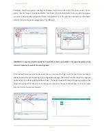
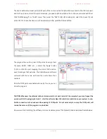
Page 37: ...er as it was previously aligned with the radio telescope antenna We continue the alignment procedure recovering from the previous paragraph A with the mount turned off loosen the clutch of the Right Ascension and Declination motions and point the an tenna towards the North Star image of radio telescope pointed to the North Star B Turn on the mount and set up all initial data as described in previo...
Page 38: ...ilter otherwise you will not see anything Most likely the star will not be perfectly centered in the finder You can use the arrow keys to move precisely the mount until the star is perfectly in the center of finder reticle the mount is set to the minimum speed of move ment to increase it click the RATE button and then a number 1 is the minimum speed 9 is the maximum we re commend using the speed 6...
Page 39: ...ce you need to check some de tails of the antenna This procedure is performed with the radio telescope and the receiver turned off First of all you need to verify that the distance between the feed horn disk and the center of the parabolic antenna is between 80 and 81cm 80 5 cm is in fact the focal length of the parabola 230cm diameter multiplied by 0 35 focal ratio Then take the Collimation rod 1...

Page 40: ...d be approximately in the center of the parabolic antenna If as in the image above it s not pointing to the antenna you can use the 3 120 Allen screws to adjust the tilt Unscrewing 2 screws and tightening the opposite one the collimation rod tilt can be adjusted slightly enough Caution do not over tighten these screws When adjusting the angle of the collimation rod make sure that the distance betw...

Page 41: ...moving the rod collimation Then you will need to check that the feedhorn support with the LNB 9 is alignmed with the parabolic antenna In order to do this you will need to activate the radio telescope and take a series of radio images of the Sun This pro cedure will then be explained later in the manual after you learn how to use the RadioUniverse control software to properly record the data from ...

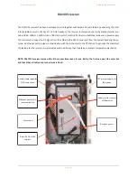
Page 42: ...he RS232 serial port from the system handling the an tenna an Ethernet port provides communication with the instrument to the PC station To optimize the stability of the radiometer the receiver is implemented within a PID loop that maintains a constant temperature electronics NOTE RAL10PL receiver comes with all the connections ready for use Before the first use open the outer box and check that a...

Page 43: ...ion of the cold sky in the absence of radio sources This parameter does not change the gain of the system and is set automatically whenever the user changes the gain of the receiver Both parameters can be modified using RadioUniverse control software as we shall see in the following paragra phs Inside the receiver there is a special electronic control unit that allows to control all components of ...

Page 44: ...s very important to disable the firewall if you have one installed in the operating system of the control computer as it prevents the scanning device In the window that opens select the device and then you can press the Skip to end the search Now you need to enable the device through the opening of the configuration web page Then select the button Web 6 a page will be opened by the default operati...

Page 45: ...n 12 to confirm the port mapping then select OK to subse quent messages that will arise The RadioUniverse software will work with these two ports and then write down their numbers Now the COM ports are enabled and ready for use you can close the program CAUTION Whenever the ethernet cable is disconnected or at each restart of the computer you must repeat the procedure ONLY in paragraphs 6 and 7 st...

Page 46: ... click on the installation file RadioUniverseSetup e xe you will get a welcome window click the Next button In the second window you can select the installation directory RadioUniverse Base is C Program Files RadioUniverse but if you want you can change this by clicking the Browse button In the next window you can specify which name to set the link in the Start menu To leave RadioUniverse click th...

Page 47: ... drivers Celestron Unified Before staring the software switch on both the receiver and the mount then connect the mount to your computer where you installed the control software Then press the Windows Start button bottom left of the screen select All Programs then the folder RadioUni verse and finally RadioUniverse It will open a registration window such as the one shown here To register RadioUniv...

Page 48: ...tude and LON longitude In the upper left choose Configuration then Radio Telescope Location This will open a window Radio Tele scope Location in which you can enter the details of your place Note You must enter the data with the correct positive or negative sign For the latitude positive values indicate the northern hemi sphere and negative in the southern hemisphere For longitude p a g e 47 Windo...

Page 49: ...d to the computer where you installed RadioUniverse Go into the Windows Control Panel and select System then Device Manager name may change depending on the version of the operating system There s a list of devices double click on COM Ports and note the COM port number associated with the receiver and the mount You can now close this window and return to RadioUniverse To activate the connection wi...

Page 50: ...COM port relative to the mount 4 Latitude enter the latitude position of the radio telescope 5 Longitude the longitude position of the radio telescope Confirm your choices by clicking OK and again OK button in the ASCOM Telescope Chooser On the RadioMap you will see a cross that indicates the location pointed to by the radio telescope Now you re ready to record radio waves coming from space p a g ...

Page 51: ...transit follow this procedure 1 Defined as the object you want to record 2 Visualize it the sky map if necessary you can view additional data by checking the options on the left Solar Sy stem Stars Horizon EQ Grid 3 Using the mouse move the arrow to the radio source that you want to resume transit click with the right mouse button and select Sync Antenna The radio telescope will point to the reque...

Page 52: ...ion RadioUniverse automatically calibrate the radiometric signal taking it back at the end of each transit at mid scale with a value around 8000 This function is useful when you want to take multiple consecutive transits of the same object if it is necessary to record to set high gain In fact due to the different height of the object with the capturing of different transits it is preferable to sel...

Page 53: ...le during a radio image it moves continuously and therefore the contribution of the noise varies and is difficult to quantify In order locate a very weak object such as Cassiopeia A and Taurus A it is thus possible to automatically record more transits moving the radio telescope in declination between transits In order to do this select a number of transits greater than 1 then set the parameter De...

Page 54: ...w to the point you wish to record click with the right mouse button and select Sync antenna The radio telescope will point to the request area of the sky 4 In the Antenna Exposure Control window select Raster image here you can set the parameters for recording of your image If Sequence is activated in the options panel on the left on Radio Map window you will find a preview of the image position a...

Page 55: ...ion of the acquisition parameters but in gene ral it is never short You can see the image that is progressively generated both on the radio map and in the An tenna Exposure Control panel You can change the way the picture is displayed also while it is being created not only at the end of the recording clicking the right mouse button on the image and select the option Greyscale or Rainbow For both ...

Page 56: ...variations is to use a calibration point outside the imaging area This point is only used to check whether with a continuous series of measures its value is constant or changes over time In order to use the calibration point move the lever to the left or right of center notice that on the RadioMap an indicator of the calibration point position appears The calibration point is set so that it lies a...

Page 57: ...s Now let s see how to adjust the system even better For a greater antenna efficiency it is necessary that the feedhorn axis is corresponding to the one of the parabolic antenna In order to fine tune this we use the technique of recording radio images of the Sun Having off the Spider230 install the solar attenuator on the receiver Then turn on the receiver and the mount connect your control comput...

Page 58: ...slightly moving the 3 or 4 holes plates support 7 and 8 Slightly unscrew the 2 screws that secure each plate on the body of the parabolic antenna and move the plate itself towards the front or the rear of the parabolic antenna You can only make a small adjustment plates have a slot that allows you to adjust the position of about 1 mm but it will suffice for this purpose Adjust the position of the ...

Page 59: ...t the ambient temperature does not exceed 35 C If during the hot summer days the direct light of the sun warms the receiver box to very high values and the temperature reading is above 44 C it is advisable to open the receiver box to allow air to cool it slightly You can also place on top of the receiver an object large enough to keep the receiver under shadow If not enough you can place a fan tha...

Page 60: ...d to the variation of the background noise are temperature variations described in the previous paragraph and variations of the antenna pointing positions If we set a high gain eg 10 point the antenna to the vertical and then move progressively towards the horizon we can see that at the radio value tends to de crease and then increase again This phenomenon is due by two main causes The first is th...

Page 61: ...e software double click on RUVIZ exe file no need for installation A window will appear like the one shown here RUviz uses special algorithms in order to to reduce the signal drift caused by the change of the antenna pointing Other features allow you to minimize the drifts due to variations in ambient temperature Select File then Open File A window will open where you can select the file RUD forma...

Page 62: ...etween one and the other transit and corrects this variation Regression Offset within a single transit the variation of the working temperature of the receiving device eg the one of LNB can lead to a progressive increase or decrease of the values This option automatically normalizes these drifts Resample RA set the image Right Ascension resolution to the same values of Declination it depends on ho...

Page 63: ...ne of transits was ruined and shows strange va lues while the others have been successfully registered you can remove only this transit In order to do so you can move the mouse cursor over the radio map corresponding to transit to delete and click with the right mouse but ton You can now save the data in graphic form image by pressing the button Save Report or in CSV format for ex ternal processin...

Page 64: ... the heat of our star and a variable one called Distur bed Sun that varies over time and depends on the presence of sunspots or flares Spider230 lets you check that the Sun emits radio waves With the radio telescope turned off install the solar atte nuator necessary because instrument high sensitivity would resolute in signal saturation if you point our star wi thout a filter Then turn on the radi...

Page 65: ... radio emission Now let s take a radio image of the Sun with a higher resolution in order to precisely verify it s emission For exam ple we can set 20 columns 20 rows resolution 0 1 and an integration time of 1 second Click the Filename but ton to select the name and the folder of the file to save So after checking that the Sun Correction option is al ways selected press the Start button to start ...

Page 66: ...ry where you in stalled RadioUniverse Here you will find a file called log_ date _ time txt that contains the saved data we now learn how to process it with software like Excel or similar After you open Excel select Data then Load External Data and then Import Text File Select the file you saved before and click the button Data p a g e 65 ...

Page 67: ... the first value in the first column and select Insert then enter the names of TIME SIGNAL and TEMPERATURE Now we need to convert the time in the right format Please add a blank column to the right of the first column click with the right mouse button on the letter B above SIGNAL and select Insert Then select the second row of the second column and write A2 2415018 5 Confirm pressing the keyboard ...

Page 68: ...nd select Select Data In the window that opens click the Add button to add a new data series Then press the button to the right of the Name field indicated by the red arrow in the photo on the left the window will become smaller click on cell C3 where it is written SIGNAL and press enter to confirm Repeat the same step for the field Y Values where you have to select all the cells in the third colu...

Page 69: ...ven by professional radio telescopes Some sources available on the Internet Nobeyama Radio Observatory http www nro nao ac jp en Australian Government Radio and Space Weather Services Learmonth Observatory http www ips gov au Solar 3 4 Ottawa 10 7cm radio flux http www spaceweather gc ca solarflux sx eng php p a g e 68 ...

Reviews: