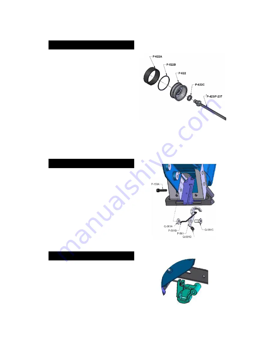
REPLACING THE DRIVING BLADE
The driving blade is sold separately or supplied as a
complete subassembly with the piston.
• Follow steps [1] & [2] of the section 'Disassembling the
tool' to remove the head assembly. Pull the cylinder out
of the main body if necessary.
• Pull-out the piston assembly.
• Remove any debris and assess condition of cylinder. If
marked or grouged, use a fine sand paper to smooth out
walls. The piston must be allowed to move without
restriction.
• Lock the piston in a vise, using a rag to prevent scoring.
Always use the top and bottom faces to secure the
piston in place.
• Remove the broken driver using a wrench.
• Put one drop of medium strength adhesive sealant onto
the threads of the piston.
• Insert the P-622C lock washer and screw the new
driving blade onto the piston. Tighten very hard.
• Remove the bumper, inspect & remove debris.
• Reassemble tool following instructions in previous
section.
INSTALLING THE SAFETY
You shouldn't need to remove the safety stop mechanism
unless the element P-561 do not swivel or has a broken
tip.
• Assemble together parts P-561, Q-061A , Q-061C and
Q-061D.
• Insert the short end of P-561B as shown.
• Put two drops of adhesive sealant onto the thread area
of Q-061C, near its cylindrical end. Make sure no
sealant is retained on the end or exterior wall.
• Insert the assembly into the hole in the tool body as
shown.
• Tight together with screw P-153A, holding Q-061C.
INSTALLING THE BASE ASSEMBLY
The plastic base can be installed or removed without the
need of a tool.
• First, insert connecting stem P-561B to the safety
contact P-562.
• Lift the safety contact and fully slide-in the plastic base
P-533 onto the brackets P-535A & B.
• The safety contact should simply drop into place. Insert
the locking rod P-562 until it snaps. It should engage the
safety contact.


