


ADJUSTING FOR HARDWOOD THICKNESS
The Q550A pneumatic tool is fitted with a fully adjustable
plastic base designed to prevent contact with the top edge
of the flooring. It is important to adjust the tool to fit the
flooring prior any installation. It also features a resting
block which prevent damage to the top edge of the
flooring by positioning the tool against the tongue,
preventing the gate/foot assembly from contacting the
board.
Step 1: adjusting the base for flooring thickness:
• Using the supplied Allen wrench, loosen but do not
remove screws (A); two on each side of the tool.
• With the tool in an upside down position, place a short
piece of flooring against the gate/foot assembly.
• Engage the Allen wrench in knob (B) as shown; rotate
to move the base up or down. Note that knob (B) has
a rotation range of only about 1/2 turn. Do not apply
force when a limit is reached.
• Adjust the height of the plastic base to obtain a small
gap between the gate/foot assembly and the top side
of the tongue of the sample board. A gap of 1/32"
should be adequate for most situations.
• Tighten both screws (A).
Step 2: adjusting the resting block for the width of the
tongue:
• Using the Allen wrench, loosen by about 1/2 turn ― do
not remove the two screws (C).
• With the short piece of flooring still against the
gate/foot assembly, adjust the gap between the resting
block and the tongue with screw (D). A small gap of
1/32" should be adequate for most situations.
• Tighten both screws (C).
• Ensure that screw (D) is slightly tighten. Do not apply
force on screw (D) once screws (C) are tighten.
After completing the adjustment procedure, proceed with
the installation of few boards. Carefully check for the
proper positioning of the fastener onto the board. Check
again after few more rows to insure that all parts are
secured in place. Tool may lose adjustment over time if
this procedure is not strictly followed.
Before starting an installation, fasten down few
boards to ascertain that the tool is properly
adjusted. Always complu with all manufacturers
recommendations.
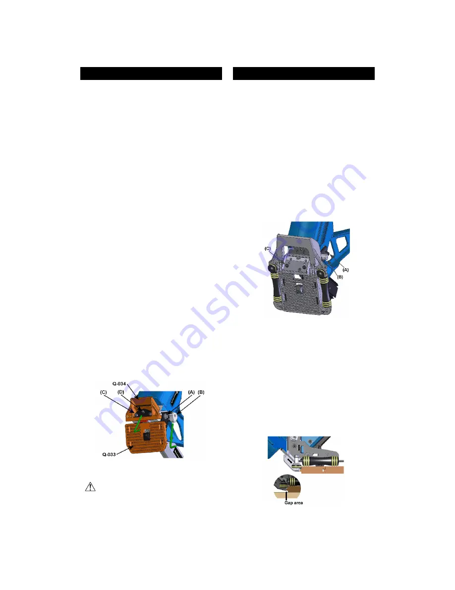
ADJUSTING ROLLER BASE
The Q550A can be mounted on a roller base (standard on
Q550AR).
Step 1: adjusting the back rollers for flooring thickness:
• Using the 3/16" wrench, unfasten but do not remove
screws (A), on each side.
• Put the tool upside down and position a short piece of
flooring against the gate/foot assembly.
• Engage the 3/16" wrench in knob (B) as shown; rotate
to move the base up or down. Note that the rotation
range is only about 1/2 turn, do not apply unnecessary
force when a limit is reached.
• Adjust the height of the base to obtain a small gap
between the gate/foot assembly and the top side of the
tongue of the sample board. A gap of 1/32", about half
the thickness of the nail, should be adequate for most
situations.
• Tighten both screws (A).
Step 2: adjusting the resting block for the width of the
tongue:
• The front rollers are always in contact with the front
edge of the board. It is necessary to adjust the resting
block to maintain a small gap between it and the tongue
of the board.
• Using the 3/16" wrench, unfasten by about 1/2 turn ―
do not remove the two screws (C).
• With the short piece of flooring still against the gate/foot
assembly, adjust the gap between the resting block and
the tongue. A small gap of 1/32", about half the
thickness of the nail, should be adequate for most
situations.
• Tighten both screws (C).


