OPERATION
Unload the tool and rest it onto the subflooring, Connect
the hose and cycle tool once or twice without fastener.
After loading the tool, it is ready for use.
Use only the hammer supplied with the tool. The use of
other type of hammers may affect performance. The
rubber face of the hammer can be used with care to help
position the boards.
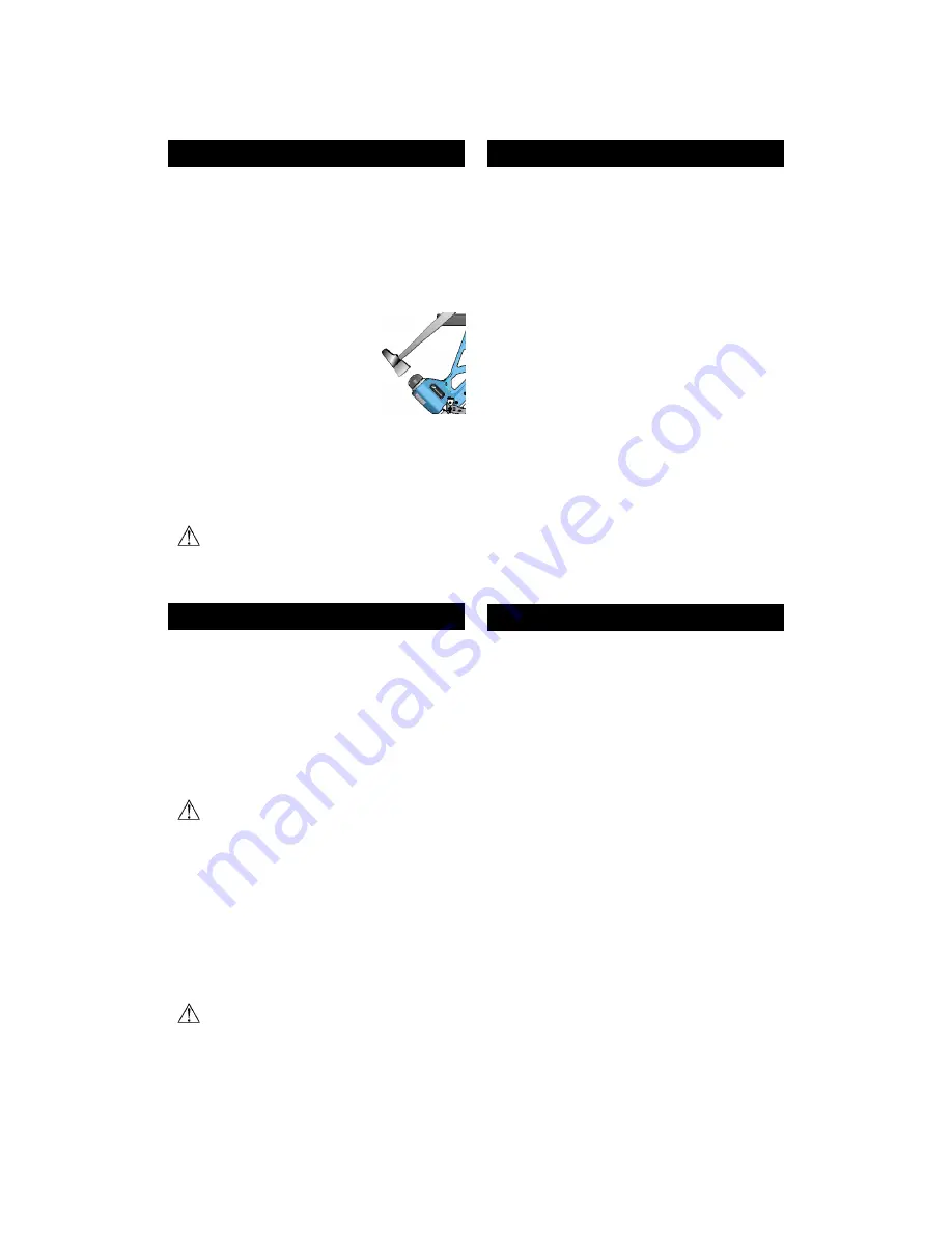
With the flooring firmly in place, position
the tool onto the flooring, with the
resting block against the tongue. Apply
downward pressure to ensure proper
seating of the fastener. Strike the head
cap with the hammer to activate the tool,
Use only the rubber face of the
hammer to activate the tool. Using
the steel end will damage the tool and void the
warranty.
If wood is slightly twisted, hitting the tool with
more force will assist in pulling the board up snugly.
Never strike the head cap when the tool is not sitting on
the working surface.
on.
Before starting an installation, fasten down
few boards to ascertain that the tool is
properly adjusted. Always comply with all
manufacturers recommendations.
MAINTENANCE & REPAIR
Most adjustments to the tool can be made with the 3/16"
Allen wrench supplied with the tool.
Disassembly of the tool must be done in a clean
environment. Some parts can be easily damaged if
disassembled with improper tools or by inadequate
methods. Maintenance should only be performed by
trained personnel. Use only genuine Primatech
replacement parts.
To prevent injury, ALWAYS disconnect the air
supply hose when servicing or disassembling
the tool.
W hen servicing the tool, do not twist or force any parts.
Damage may result from such abuse. Contact your
Primatech distributor for more information.
When opening the tool for maintenance, always clean all
components of dirt, grit, or particles. Inspect the tool
carefully for broken parts or excessive wear, and replace
if necessary. When ordering parts, be sure to specify the
right part number, as well as the tool serial number.
After any maintenance to the tool, REMOVE
ALL Fasteners before connecting air and
actuate the tool repeatedly over a piece of
wood or subflooring to insure proper
operation.
DISASSEMBLING THE TOOL
All pneumatic components required are packed in a
module assembly which is simply inserted & removed
from the tool. This section describes how to disassemble
the tool to access its internal components.
[1] Loosen up the head lock and rotate it ¼ turn to
disengage it from the head.
[2] It is usually not necessary to remove the head cap.
Simply unscrew the head completely and take out the
whole assembly. You may engage the long arm of the
Allen key into one of the side holes and use it as a
lever.
[3] Pull out by hand the cylinder from the head. Do not
use screwdriver or vise. If the cylinder remains into the
main body, pull it out of it.
[4] Pull out the valve assembly from the head. Inspect
wear ring & lubricate. Do not attempt to disassemble
the valve assembly.
[5] Pull out the piston assembly; the bumper will also
come with it. Inspect wear ring and lubricate.
It is usually not necessary to pull-out the seal bushing
for maintenance.
CLEANING THE VALVE
If the tool becomes sluggish or does not set the fastener
correctly, it may indicate excessive dirt, dust, other
particles, or even water, in the tool. The first step in
troubleshooting is to clean up the head assembly.
• Disassemble the head assembly as described in
previous section.
• Perform a visual inspection of the valve assembly.
Ensure that the actuator is sliding easily. Clean and
lubricate lightly. Do not attempt to take apart the actuator
assembly.
• Clean the inside wall of the head and lubricate lightly
with a non-detergent oil. Insert the valve assembly into
the head and ensure that it is sliding easily.
• Ensure the piston assembly is sliding easily into the
cylinder. It should offer some resistance, but if it moves
too easily, it may be required to replace the piston wear-
ring.