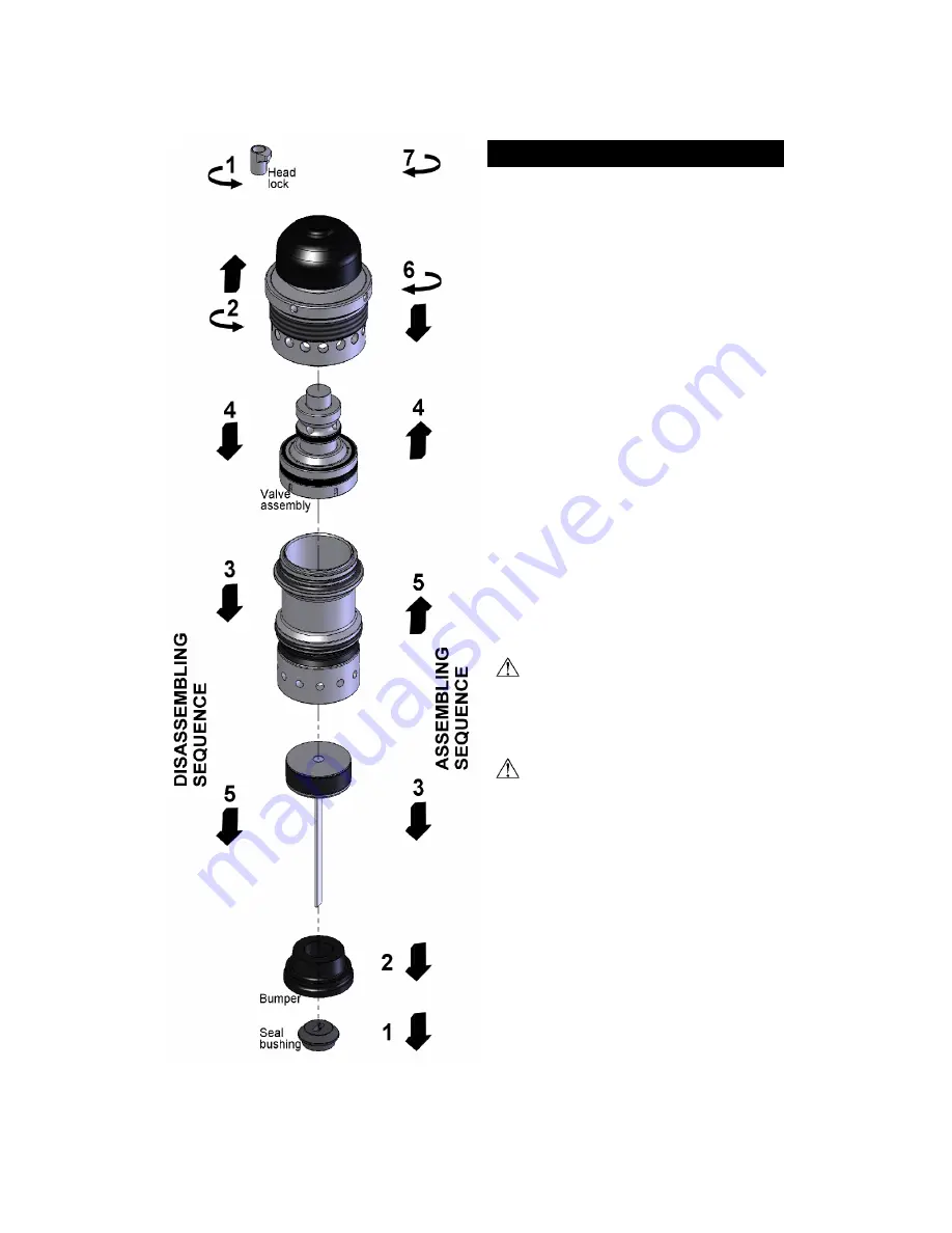
background image

ASSEMBLING THE TOOL

This section describes how to re-assemble the tool after
maintenance. The following procedure assumes that the
gate/foot  assembly  along  with  the  resting  block  are
already installed.

[1] Insert the seal bushing in the lower section of main

body  and  engage  it  onto  the  upper  portion  of  the
gate/foot assembly. A flat screwdriver can help locate
it correctly. Use the wooden handle of the hammer to
tap the seal bushing completely in place.

[2] Check & lubricate the valve assembly. Insert into the

head and ensure that it is sliding easily.

[3] Snap the cylinder onto the head. Check that the band-

valve on the cylinder is properly installed.

[4] Insert the piston assembly about 1" into  the bottom

end of the cylinder.

[5] Push the bumper into the bottom end of the cylinder.

[6] With  the  head  lock  loosened,  engage  the  whole

assembly into the tool, with the driving blade engaged
thru  the  opening  of  the  seal  bushing.  Depress  the
safety  contact  and  engage  down  completely  into
gate/foot assembly guiding channel.

Insert  the  Alen  key  into  one  of  the  side  holes  and
screw the head assembly completely.  Take care not
do damage the threads. Tighten by hand.

NEVER apply threadlocker or adhesive onto
head threads.

[7] Rotate  the  head  lock  clockwise  and  tighten  with

moderate force with the Allen key.

After reassembly, always actuate the tool
repeatedly WITHOUT FASTENERS against a
piece of wood to insure proper operation.

Summary of Contents for Q550A

Page 1: ...hit the head cap of the actuator if the plastic base is not sitting perfectly on the working surface Never leave the tool laying down on its side while the air supply hose is connected the tool shoul...

Page 2: ...e adjustment procedure proceed with the installation of few boards Carefully check for the proper positioning of the fastener onto the board Check again after few more rows to insure that all parts ar...

Page 3: ...te at 70 F 21 C Higher air pressure will increase the consumption of compressed air This tool is designed to be operated with a compressed air pressure of 80 to 100 psi 5 5 7 0 bar Air pressure of 80...

Page 4: ...e if necessary When ordering parts be sure to specify the right part number as well as the tool serial number After any maintenance to the tool REMOVE ALL Fasteners before connecting air and actuate t...

Page 5: ...valve on the cylinder is properly installed 4 Insert the piston assembly about 1 into the bottom end of the cylinder 5 Push the bumper into the bottom end of the cylinder 6 With the head lock loosened...

Page 6: ...nt is retained on the end or exterior wall Insert the assembly into the hole in the tool body as shown Tight together with screw P 153A holding Q 061C INSTALLING THE BASE ASSEMBLY The plastic base can...

Page 7: ...apply to all parts except those subjected to normal wear SEVEN YEAR EXTENDED LIMITED WARRANTY covers tool casing WARRANTY STATEMENT Primatech s sole liability hereunder will be to replace any part or...

Reviews: