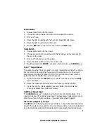
LED Indicator
1. Discuss placement with the owner.
2. Choose a location that is visible from both sides of the vehicle.
3. Drill a ¼" hole.
4. Route the LED wires through the hole and press LED into place.
5. Route the LED wires to the control unit.
6. Plug the RED LED connector into the control unit RED plug.
Valet Switch
1. Discuss placement with the owner.
2. Choose a location for the valet switch that is hidden, but convenient for
the owner to access.
3. Drill a ¼" hole and mount the switch.
4. Route the valet switch wires to the control unit.
5. Plug the valet switch WHITE connector into the control unit WHITE plug.
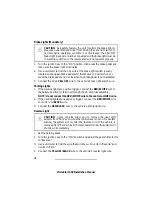
Zone
2
™ Impact Sensor
The sensor must be firmly mounted on a solid metal surface inside the vehicle.
We recommend tie wrapping the sensor to the steering column housing or
steering column support bracket. DO NOT mount the sensor near moving
parts or in the direct path of an air duct opening.
1. Plug the impact sensor BLUE 4-pin connector into the control unit BLUE
4-pin connector.
2. Route the impact sensor harness to the chosen mounting location.
3. Using the long tie wraps supplied, securely fasten the impact sensor
allowing access to the adjustment screws.
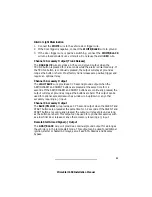
Additional Sensor Input
The ORANGE wire is a (-) trigger input with a 5 second arming delay. This
input can be used for optional sensors such a glass sensor, radar sensor or any
other type of sensor that provides a (-) ground output when triggered.
Alarm Armed Signal (-) Output
The GRAY wire will provide a continual 300 M.A. output whenever the alarm is
armed. This output can be used for voice modules, window roll-up modules and
any other optional accessory that requires a (-) output when the alarm is armed.
9
PrimeStart 650 Installation Manual
Summary of Contents for PrimeStart 650
Page 1: ...PrimeStart 650 Installation Manual...
Page 2: ...PrimeStart 650 Installation Manual...
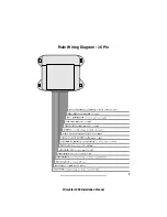
Page 5: ...3 PrimeStart 650 Installation Manual Main Wiring Diagram 16 Pin...
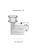
Page 6: ...Main Wiring Diagram 12 Pin 4 PrimeStart 650 Installation Manual...
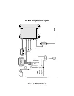
Page 7: ...5 PrimeStart 650 Installation Manual Satellite Relay Module Diagram...
Page 20: ...18 PrimeStart 650 Installation Manual...
Page 21: ...19 PrimeStart 650 Installation Manual...

