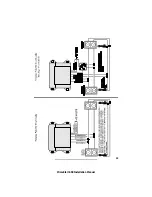
Interior Light Illumination
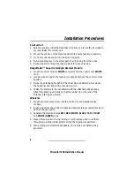
1. Connect the WHITE wire to the vehicle door trigger wire.
2. If the door trigger is negative, connect the WHITE/BLACK wire to ground.
3. If the door trigger wire is positive switching, connect the WHITE/BLACK
wire to a fused constant +12 volt source. Do note use the alarm RED wire.
Channel 2 Accessory Output (Trunk Release)
The DARK BLUE wire provides a 0.75 second ground output when the
TRUNK button is pressed for 1-2 seconds while the alarm is disarmed only. If
the TRUNK button is continually pressed, the output will stay at ground as
long as the button is held. Most factory trunk releases are positive trigger and
require an optional relay.
Channel 6 Accessory Output
The LIGHT BLUE wire provides a 0.75 second ground output when the
ARM/DISARM and SILENT buttons are pressed at the same time for 1-2
seconds. If the ARM/DISARM and SILENT buttons are continually pressed, the
output will stay at ground as long as the buttons are held. This output can be
used for optional accessories such as window roll-up/down or any other
accessory requiring a (-) input.
Channel 9 Accessory Output
The BLUE/YELLOW wire provides a 0.75 second output when the SILENT and
START buttons are pressed at the same time for 1-2 seconds. If the SILENT and
START button are continually pressed, the output will stay at ground as long
as the buttons are held. This output can be used for optional accessories such
as a fuel filler door release or any other accessory requiring a (-) input.
Remote Start Armed Signal (-) Output
The GRAY/BLACK wire will provide a continual ground output for as long as
the vehicle is in the remote start mode. This output can be used for additional
ignition, starter or heater/AC relays, as well as VATS, Passlok and Passkey
bypass.
11
PrimeStart 650 Installation Manual
Summary of Contents for PrimeStart 650
Page 1: ...PrimeStart 650 Installation Manual...
Page 2: ...PrimeStart 650 Installation Manual...
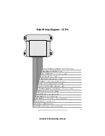
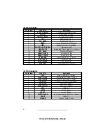
Page 5: ...3 PrimeStart 650 Installation Manual Main Wiring Diagram 16 Pin...
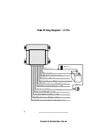
Page 6: ...Main Wiring Diagram 12 Pin 4 PrimeStart 650 Installation Manual...
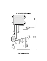
Page 7: ...5 PrimeStart 650 Installation Manual Satellite Relay Module Diagram...
Page 20: ...18 PrimeStart 650 Installation Manual...
Page 21: ...19 PrimeStart 650 Installation Manual...


