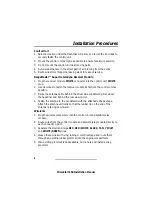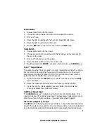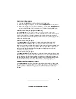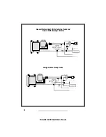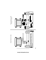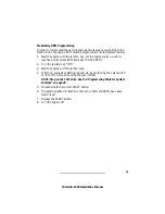
Tach Wire (RPM Monitoring)
The PrimeStart is designed to monitor the vehicle RPM by connecting directly
to the vehicle tachometer wire which is usually located at the distributor,
ignition coil or diagnostic plug. On most vehicles, the tach wire is easily
accessible. If the tach wire is not accessible, there are several alternative
choices. Contact Prime Technical Support Department for alternate choices.
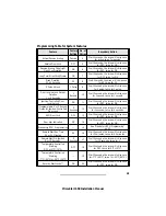
The following procedure for testing the vehicle tach wire is not exact and may
vary with different vehicle make, model and year. We recommend that you
refer to your AviFax documents for tach color code and location information.
1. Set your voltmeter to the AC voltage scale.
2. Start the vehicle. Use the voltmeter to find a wire that will show 1 to 5
volts AC while the vehicle is idle and increase an additional 1 to 5 volts
AC when the engine RPM is raised to 3000-4000 RPM.
3. Connect the WHITE/LIGHT GREEN wire to the vehicle tach wire.
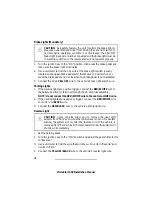
Hood Switch (Mandatory)
As a safety precaution, the hood switch prevents the vehicle from starting
when the hood is open. If the vehicle is in the remote start mode and the hood
is opened, the remote start will immediately shut down. The hood switch will
also trigger the alarm when opened.
1. Choose a location under the hood away from direct exposure to water or
water drain areas.
2. Check for proper hood clearance.
3. Make sure the hood switch will make contact with a flat surface on the
hood when closed.
4. Drill a
5
/
16
" mounting hole.
5. Mount the hood switch.
6. Connect the TAN wire to the hood switch.
7. Make sure the hood makes contact with hood switch when closed and
presses the hood switch straight down to prevent wear.
21
PrimeStart 650 Installation Manual
Summary of Contents for PrimeStart 650
Page 1: ...PrimeStart 650 Installation Manual...
Page 2: ...PrimeStart 650 Installation Manual...
Page 5: ...3 PrimeStart 650 Installation Manual Main Wiring Diagram 16 Pin...
Page 6: ...Main Wiring Diagram 12 Pin 4 PrimeStart 650 Installation Manual...
Page 7: ...5 PrimeStart 650 Installation Manual Satellite Relay Module Diagram...
Page 20: ...18 PrimeStart 650 Installation Manual...
Page 21: ...19 PrimeStart 650 Installation Manual...


