5
4
SAFETY
SAFETY
SAFETY LABELS
This pneumatic fastening tool includes a warning label to help remind you of
important safety information when operating the tool. The safety label must be
legible at all times, and must be replaced if it becomes worn or damaged.
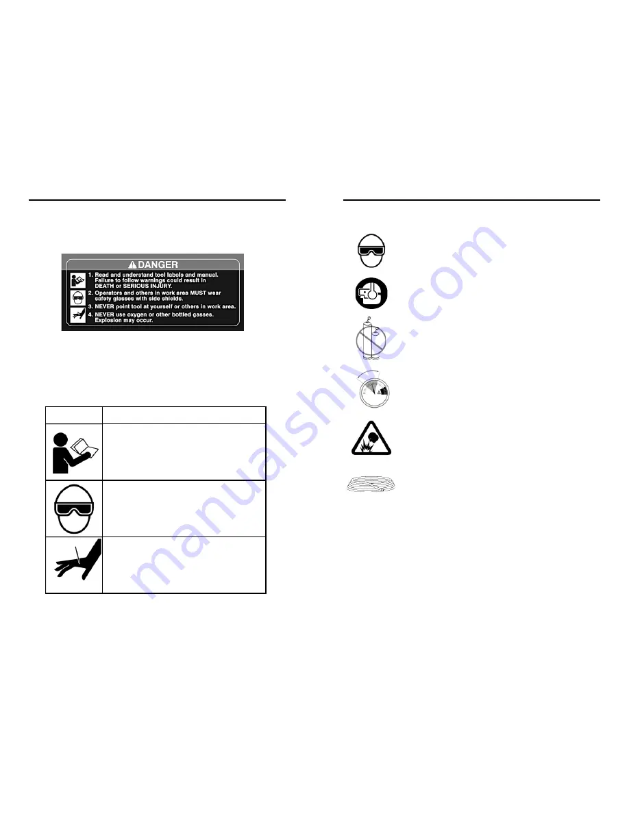
SAFETY SYMBOLS
The safety symbols on the safety label provide a visual reminder of
basic safety rules, and the personal injury hazard that may arise if
all safety and operating instructions are not followed. Make sure
you understand the meaning of each of these symbols, and protect
yourself and others by obeying all safety and operating instructions.
SYMBOL
DESCRIPTION
READ THE MANUAL
- The manual contains
important safety and operating instructions
that must be followed. All tool users must
read the manual before using the tool.
WEAR SAFETY GLASSES
- Tool operator
and bystanders must wear safety glasses
with side shield that meet ANSI Z87.1
requirements.
RISK OF PERSONAL INJURY
- Failure to
follow all safety and operating instructions,
or misuse of the tool, can result in serious
injury to tool operator and bystanders.
WEAR SAFETY GLASSES
Always wear safety glasses with side shields that meet ANSI
Z87.1 requirements when operating the tool. Make sure all
others in work area wear safety glasses.
WEAR HEARING PROTECTION
Wear hearing protection to protect your hearing from noise.
Prolonged exposure to loud noise can result in hearing loss.
NEVER OPERATE THE TOOL WITH OXYGEN OR OTHER
BOTTLED GASES
Oxygen and other reactive or high-pressure bottled gases
can cause the tool to explode. Use clean, dry regulated
compressed air from a properly operating air compressor.
DO NOT EXCEED MAXIMUM RECOMMENDED OPERATING AIR
PRESSURE OF 120 PSI /8.3 Bar.
Exceeding the maximum recommended air pressure can
cause the tool housing to burst, or cause premature failure of
components.
NEVER CONNECT THE TOOL TO AN AIR SUPPLY THAT HAS
THE POTENTIAL TO EXCEED 180 PSI/12.4 Bar.
Using a regulated air supply with a line or tank pressure
greater than 180 psi can cause the tool to burst if the air line
regulator fails suddenly.
USE AN AIR HOSE RATED FOR 180 PSI/12.4 Bar OR
GREATER
Always use air hose rated to handle 180 psi or the maximum
potential pressure of the air supply.
ONLY USE A RELIEVING-TYPE AIR COUPLING IN THE TOOL
AIR INLET OPENING.
Use of a non-relieving air coupling on the tool can trap air
inside the tool housing, and allow the tool to drive a fastener
even after the air hose has been disconnected.
SAFETY INSTRUCTIONS
120 psi
6.9 bar
100 psi
8.3 bar


