11
PRIMERGY BX600 S2 Blade Server System Unit Hardware Guide
1
C
o
mpon
ent N
a
mes a
nd
F
u
nctions
6
3.5-inch storage bay
Contains a BX620 S2 Server Blade internal hard disk
unit.
The expansion card slot module (optional) can be
installed to bay 2.
7
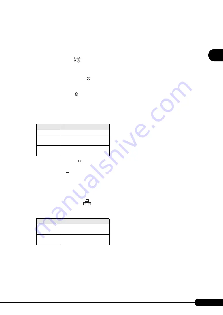
Hard disk status LED (
)
Displays the status of the hardware disk unit installed
where the LED is positioned.
The meaning of various LEDs is as follows.
Hard disk access display LED (
)
This LED is lit in green when data is being written to
or read from the hard disk.
Hard disk failure LED (
)
In an array system configuration, this LED is lit in
amber when an error is detected in the internal hard
disk unit.
This LED lights or blinks depending on the status of
the hard disk as follows.
8
Server blade power LED (
)
9
Server blade power switch
10
KVM select LED (
)
11
KVM select switch
Selects the keyboard/display/mouse.
12
Fibre Channel active link display
LED (
)
13
LAN active link display LED (
)
This LED lights or blinks depending on the status of
the server blade LAN transmission as follows.
14
Display/USB expansion connector
15
2.5-inch storage bay
Contains a BX620 S3 Server Blade internal hard disk
unit.
LED status
Hard disk status
OFF
In normal mode or hot spare mode
ON
(Amber)
Error detected in the hard disk (in
an array configuration)
Blinking
(Amber)
Rebuilding or faulty hard disk
replacement in progress
I/O
LED status
Server status
ON (Green)
Establishing link at either LAN
port
Blinking
(Green)
Sending/receiving data via LAN
16
Expansion card slot
When an Expansion Card Slot Module has been selected
in the BX620 S3 Server Blade, an expansion card can be
installed.


