background image


22 


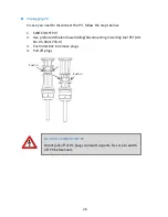
Ripple Control Receiver (RCR)/RS485 and RJ45 Connections  

1.


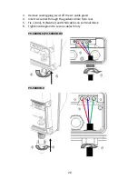
Remove sealing plug and twist off the cable gland (M25) 

2.


Insert wires from rear of guidance and holes of rubber sealing (M25) 

3.


Refer to Ch.9 on P.48 for proper RS485 connections 

4.


Refer to Ch.10 on P.51  for proper RCR connections 

5.


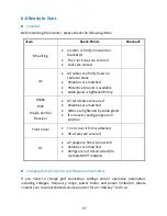
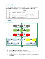
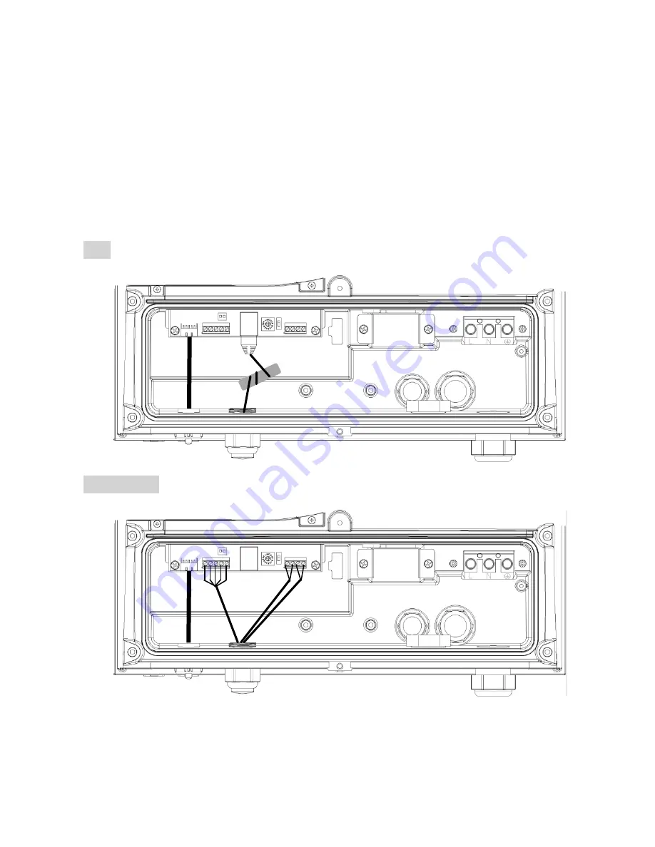
Connect RCR/RS485 and RJ45 wires as shown below 

6.


Make sure RJ45 wires is wound through a grey EMI core (from accessary kit), 
as for noise immunity 

7.


Tighten cable gland to secure cables firmly in position 

RJ45 


RS485 & RCR 


EMI Core


Summary of Contents for PV-5000W-HV

Page 1: ...Ver 1 0 EN NOV 2017 Printed on Recycled Paper SINGLE PHASE ON GRID PV INVERTER PV 3000N V PV 5000W V PV 5000W HV Installation Operation Manual...

Page 2: ...ar power conversion only do not use for other DC sources or conversion purposes Hot Surface Metallic parts of enclosure may be hot during operation Recycle Do not throw this electronic device in a tra...

Page 3: ...ntact Information Asian Power Devices Inc Trade mark PrimeVOLT TEL 886 2 2695 5388 FAX 886 2 2693 1009 ADD 11F No 211 Nanyang St Xizhi Dist New Taipei City 221 TAIWAN Official Website http www primevo...

Page 4: ...2 Installation faults such as improper environment wiring and applications 3 Working conditions beyond specified 4 Improper operation of unit 5 Violation of safety instructions in this manual 6 Damage...

Page 5: ...nting Procedure 15 6 5 Wire Connections 17 6 6 Ready to Start 27 7 Operation S Series 29 7 1 Overview 29 7 2 Setting Clock 30 7 3 Status LED 32 7 4 Frames 32 7 5 Network and Internet 36 7 6 Browsing I...

Page 6: ...generate DC power 2 DC Switchboard Links between PV panels and PV inverter include of DC switch and surge protection 3 Inverter s DC Switch PV Inverter with DC Switch 4 PV Inverter Converts DC power b...

Page 7: ...6 5 Product Overview PV 3000N V Status LED Front Cover AC Cable Gland Signal Cable Gland DC Switch DC PV Inputs Display LCD Button LED 330 mm 196 mm 375 mm...

Page 8: ...7 PV 5000W V Button LED Display LCD Status LED Front Cover AC Cable Gland Signal Cable Gland DC Switch DC PV Inputs 418 mm 190 mm 485 mm...

Page 9: ...8 PV 5000W HV Signal Cable Gland Button LED AC Cable Gland Status LED Display LCD DC PV Inputs DC Switch Front Cover 328 mm 218 mm 383 mm...

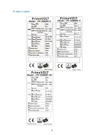
Page 10: ...9 Product Labels...

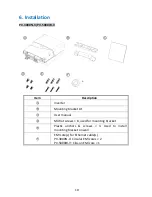
Page 11: ...ption Inverter Mounting bracket kit User manual M4 flat screws 8 used for mounting bracket Plastic anchors screws 3 Used to install mounting bracket on wall EMI core s for Ethernet cable s PV 3000N V...

Page 12: ...11 PV 5000W HV Item Description Inverter Mounting bracket kit User manual M4 flat screws 8 used for mounting bracket Plastic anchors screws 3 Used to install mounting bracket on wall...

Page 13: ...12 6 1 Assembly Chart...

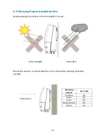
Page 14: ...the inverter in direct sunlight or to rain Mount the inverter in vertical direction tilt or horizontal mounting should be avoided Mounting Surface OK or NO Concrete OK Metal OK Stone OK Plastics Acryl...

Page 15: ...ng Properly Orientation Keeping Clearance To retain the good cooling condition keep each of unit over 20cm left and right 30cm upper and down and ensure no any object is put around the units to affect...

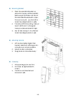
Page 16: ...bracket is used to support inverter on wall Refer to the recommendations below to complete mounting Assembling Bracket Before fixing on wall assemble the bracket as below use M4 flat Screws x 4 item...

Page 17: ...e at least 3 drill holes in a triangular manner as demonstrated on right 3 Use item torque 1 0 1 2Nm to install mounting bracket on wall Attaching Inverter 1 Lift inverter slightly higher than bracket...

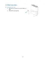
Page 18: ...17 6 5 Wire Connections Opening Front Cover 1 Remove the 4 screws on cover as shown on right 2 Take off the cover gently...

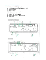
Page 19: ...es 2 Cable Gland M25 Ethernet RS485 RCR cables 3 AC terminal block 4 RS485 terminal 5 RS485 terminal resistor switch 6 RS485 address selector 7 RJ45 port for Internet access 8 Ripple Control receiver...

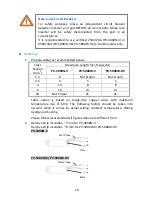
Page 20: ...erature Wiring nearby and Cooling Please follow local standards if figures above are different from 2 Remove strip insulation 7 mm for PV 3000N V Remove strip insulation 8 mm for PV 5000W V PV 5000W H...

Page 21: ...ug twist off the AC cable gland 4 Insert AC cables through the guidance hole from rear 5 Fix L Line N Neutral and GND cables on terminal block 6 Tighten cable gland to secure cables firmly PV 3000N V...

Page 22: ...les to ensure steadfastness of cables on terminal block If stranded wires are used apply core end materials enclosed in accessory kit for all sakes Torque Information The torque for AC terminal is bet...

Page 23: ...es of rubber sealing M25 3 Refer to Ch 9 on P 48 for proper RS485 connections 4 Refer to Ch 10 on P 51 for proper RCR connections 5 Connect RCR RS485 and RJ45 wires as shown below 6 Make sure RJ45 wir...

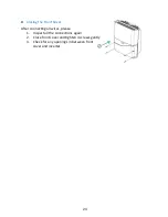
Page 24: ...Closing the Front Cover After connecting all wires please 1 Inspect all the connections again 2 Close front cover and tighten 4 screws gently 3 Check for any openings in between front cover and invert...

Page 25: ...String 20 in Total 10 String 1 2 1 2 Use either of the following recommended connectors 1 Wieland PST40i1C Preferred 2 Multi Contact MC4 3 Connect to PV After all the associated cables and connectors...

Page 26: ...er will adjust to optimal performance accordingly by itself Keep the Sealing Plugs Please keep those plugs in a safe place You may need to use them again in case removal of DC connectors is needed Rem...

Page 27: ...1 SWITCH OFF PV 2 Use preferred Wieland assembling disconnecting mounting tool PST Art No 05 502 1753 0 3 Push interlock to release plugs 4 Pull off plugs Be Sure to SWITCH OFF PV Direct pull off of D...

Page 28: ...iver All terminals are secured Polarities are matched Wires are tightened by cable gland If not used sealing plugs are in position Front Cover Front cover is firmly attached All screws are secured DC...

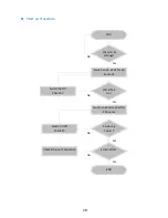
Page 29: ...hecklist Settings Switch on AC Wait for 40 Seconds LCD Tab On Switch AC Off Check AC Switch on PV DC Wait for 2 Minutes Producing Power Switch PV Off Check PV Ethernet OK Check Ethernet Connection END...

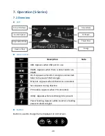
Page 30: ...o manual of Wi Fi dongle Ethernet Appears when Ethernet is connected Sun Appears during daytime PV module Appears when PV connected Utility Appears when electrical grid is present Power feeding Appear...

Page 31: ...frame Forward Switches to next daily monthly frame 7 2 Setting Clock During the first installation of inverter where the internal clock has not been set the system will automatically prompt user to s...

Page 32: ...rame to make adjustments afterwards Keeping the Clock Settings In cases where the AC has been disconnected for more than 3 5 hours the internal clock of inverter will roll back to factory default sett...

Page 33: ...lt 7 4 Frames Operation Chart Daily Frame Home Screen Next Day Info Previous Day Info Monthly Frame Next Month Info Previous Month Info Daily Error Frame Next Daily Error Previous Daily Error E TOTAL...

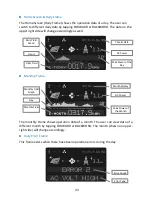
Page 34: ...hly Frame shows operation data of a month The user can view data of a different month by tapping FORWARD or BACKWORD The month shown on upper right side will change accordingly Daily Error Frame This...

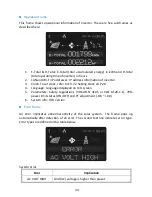
Page 35: ...r to Ch 7 2 Setting Clock on P 28 4 Language Language displayed on LCD screen 5 Parameters Safety regulations VDE AR N 4105 or VDE 0126 1 1 70 power limit status ON OFF and PF adjustment 0 8 0 8 6 Sys...

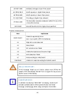
Page 36: ...ser must switch off PV immediately C1 High DC current detected C2 Relay failed C3 DC current sensor failed C4 Internal temperature of inverter high C5 GFCI detection failed C7 Anti islanding or AFD fa...

Page 37: ...erter with the router as well Use touch pad to go to Operation Frame for IP confirmation Accessing Inverter via Internet The illustration above demonstrates how to access the inverter via Internet Sim...

Page 38: ...s IP address 3 Open a web browser on your desktop laptop key in the IP address you have read previously at the address bar Refer to figure below The example IP address here is 192 168 10 122 4 Daily...

Page 39: ...Showing current operation status During the night and or when inverter is not working the area is black When an error or failure happens a message will pop up 3 Information Board Displays power genera...

Page 40: ...nd F W version 2 Time Date Clock of inverter You can set the time zone and synchronize with time server automatically 3 Voltage Range Operation voltage range of inverter 4 Frequency Range Frequency ra...

Page 41: ...er your user account to set up your inverters for cloud monitoring RCR Information By clicking on Show on the right of RCR Info the current settings of RCR will show up like the table next page K1 K2...

Page 42: ...fallback is an operation state which the inverter can enter if relays K1 K4 is not active in the table 6 Fallback Active When selected fallback will take place 7 Fallback Time The time required if the...

Page 43: ...in the USB all data stored in the inverter will be downloaded to the stick automatically During the download USB icon will be blinking After downloading while USB icon stays solid you can then safely...

Page 44: ...set the PF and 70 power limit Please contact your local service provider Capacity of Memory The internal memory of inverter can store up to 3 year length of data Data older than 3 year will be overwri...

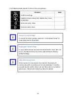
Page 45: ...ge current energy of today totally energy totally operation time regulation setting model name and firmware version Button icon Icon Description Note LED A Reference LED fault table A LED B Reference...

Page 46: ...GFCI Detection Failed OFF ON ON Bus Failed Blink OFF OFF Isolation Fault OFF Blink OFF Leakage Current High OFF OFF Blink Cooling Fan s Failed Note Blinking means LEDs on for 0 5 seconds and off for...

Page 47: ...ed today unit kWh Push the button on LED panel gently to change inverter information frame on LCM screen Please refer to flow chart on next page for sequence of on screen inverter information frames W...

Page 48: ...e mentioned above will be recorded in history error information frame Refer to the table below for interpretation of all inverter error messages System error Error Message Indication AC VOLT HIGH Vac...

Page 49: ...tion failed FAN FAILS Fan not working properly Inverter internal error 2 Error Message Indication F1 Bus voltage low F2 Bus voltage high F3 CPU communication abnormal F4 Mismatch of firmware version b...

Page 50: ...uter shall be twisted 2 Maximum allowable wire length is 1000 meters 3 The terminal end device should have a terminal resistor 4 Due to multiple connections each individual device should be assigned a...

Page 51: ...s please assign them different positions with no duplications Since only 15 positions 1 F are available the maximum number of inverters that can be grouped at a time in a RS485 bus is 15 Position 0 is...

Page 52: ...ives control signals from your power company PV series inverters can be connected to RCR directly Inverters will be able to receive command from RCR and adjust their AC output powers to the correspond...

Page 53: ...52 Connections with Single Inverter When connecting a single inverter only refer to the figures below Connections with Multiple Inverters To Other Inverters...

Page 54: ...o keep the inverter in best performance it s recommended to do the following on a regular basis 1 Make sure no object is placed on the top of inverter 2 Dust off the inverter especially the heat sink...

Page 55: ...V polarity 3 Check PV voltage 160Vdc 4 Wait for stronger sunlight Error on display 1 Refer to error table in Error Frame section 2 Error other than C Read related meaning and take suitable action 3 C...

Page 56: ...r W 3000 5000 3 5000 3 Max Power W 3000 5000 4 5000 4 Nominal Voltage V 220 230 240 Voltage Range V 184 264 5 6 Nominal Frequency Hz 50 60 Power Factor 0 8 0 8 Maximum Current A 14 3 23 8 5 23 8 5 Max...

Page 57: ...adjust inverter parameters and settings Clock Sync Automatically sync with time server Mechanical W x H x D mm 330x375x196 418x485x190 330x383x218 Weight kg 12 22 15 Input Pairs 1 2 1 DC switch Built...

Page 58: ...PV 3000N V PV 5000W V 90 91 92 93 94 95 96 97 98 0 500 1000 1500 2000 2500 3000 Pac W 330VMPP 350VMPP 370VMPP 400VMPP 450VMPP 500VMPP 90 91 92 93 94 95 96 97 98 0 1000 2000 3000 4000 5000 Pac W 300VMP...

Page 59: ...58 PV 5000W HV 86 88 90 92 94 96 98 0 1000 2000 3000 4000 5000 Pac W 550V 600V 650V 710V 750V 800V...

Reviews: