Air X Owner’s Manual
5-5 Fuses, Circuit Breakers and Ammeter
Air X is capable of producing high amperages. As with all electrical installa-
tions, you must protect each of your turbines with a fuse or circuit breaker.
Wire Air X with an appropriate size “slow-blow” fuse or circuit breaker
between it and the batteries. Refer to installation figures at the start of
Sec-
tion 5
. If a stop switch is used, the fuse or circuit breaker should be placed
between the switch and the batteries.
Recommended Sizes for Circuit Breakers or Slow-Blow Fuses
•
12-volt model: 40 amp DC
•
24-volt model: 20 amp DC
•
48-volt model: 10 amp DC
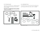
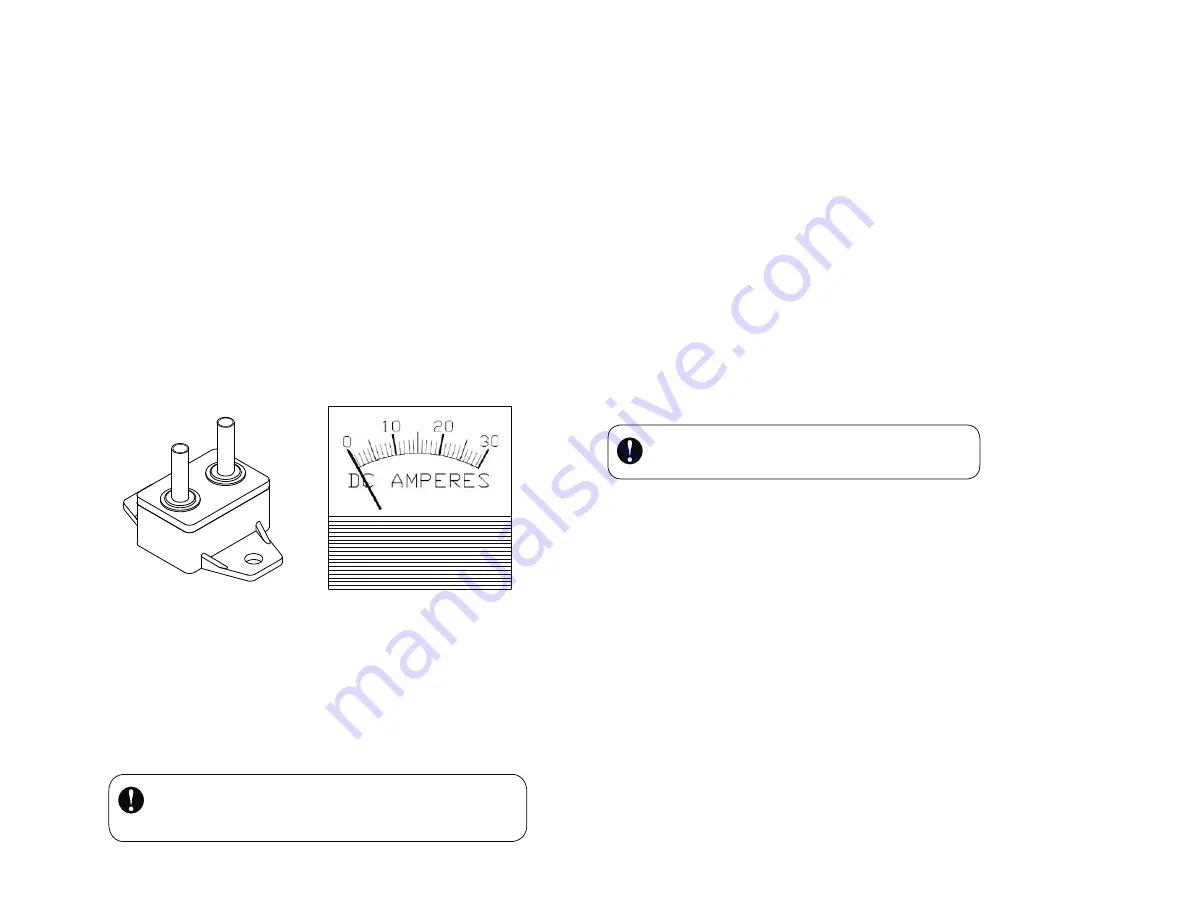
Circuit Breakers are available from
. Part numbers are
listed above.
5-6 Batteries
There are many battery choices available – flooded lead acid, absorbed
glass mat (AGM), gel cell and NiCad. The type of battery utilized will de-
pend largely on the battery bank location and cost. For battery installations
where fumes can be safely ventilated and the potential for acid leakage
accommodated, the flooded lead acid battery is typically the most economi-
cal choice.
Minimum recommended battery bank size:
• 12-volt systems –
400 Amp-hours
• 24-volt systems – 200 Amp-hours
•
48-volt systems – 200 Amp-hours
There are several informative web sites with battery information including:
• ww
w.batterycouncil.org
• ww
w.windsun.com/Batteries/Battery_FAQ.htm
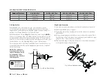
Fig. 16 Ammeter
(Amp Meter)
PN 2-ARAC-102
Fig. 15 Circuit Breaker
IMPORTANT:
Never use “automotive” batteries or any battery
other than a “deep-cycle” battery.
5-7 Turbine Grounding
Proper grounding of the Air X provides protection to individuals and equip-
ment by eliminating the possibility of dangerous voltage potentials.
There are two aspects to grounding any electrical system – grounding one of
the conductors of the electrical system and grounding all metal structures in
the system that may have a voltage potential caused by an electrical failure.
In a typical Air X installation grounding one of the conductors is accom-
plished by connecting the Air X negative (black) conductor to an “earth”
ground close to the battery bank. Installation and connection to grounding
rods is described in the following section on Tower Grounding.
Grounding the metal structures in the system – typically this includes the
tower and turbine – is accomplished by connecting the structures together
using conductors of the same size as the positive and negative conductors
and then routing a conductor to an earth ground.
While not necessary, an ammeter (sometimes called an Amp Meter) is an
excellent addition to any system. The Amp Meter allows you to monitor the
current output of your turbine. Place it in between your turbine and the bat-
tery on the positive lead. It will give you instantaneous readings of output in
amps.
The Air X emits a small, high-frequency AC ripple, possibly causing
compatibility issues with some battery monitoring systems. Use of an AC
filtering device is suggested in these circumstances.
Primus Wind Power
21
TIP
:


