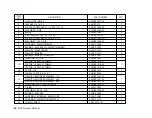
background image


ITEM 

NO.

DESCRIPTION

PART NUMBER

QTY.

1

NOSE CONE - 

3-CMBP-1007-02

1

2

JAM NUT 5/8-18 - SS

3-HDNT-912

1

3

SCREW - SOCKET HEAD - 1/4-20 X 7/8" - SS

3-HDBT-1000-04

6

4

MACHINED - HUB

3-CMBP-1005-02

1

5

BLADE

3-CMBP-1008

3

6

NUT - NYLOCK - SAE - SS - 1/4"-20

3-HDNT-102-10

6

7

SCREW - SOCKET HEAD - 10-24 X 1-1/2"

3-HDBT-1000-577

3

8

MACHINED - FACE - AIR

3-CMBP-1003-02

1

9

SNAP RING - 44MM INTERNAL

3-CAOT-1005

1

10

BEARING - 6203-RLBZD - SEALED/SHIELDED

3-CABR-1002

1

11

WASHER - WAVE SPRING

3-CAOT-1012

2

12

WASHER - BEARING

3-CAOT-1227

2

13

BEARING - 6203-ZZ - SHIELDED

3-CABR-1001

1

14

ISOLATOR - STATOR

3-CMBP-1341

1

15

STATOR - 16 AWG 10 TURNS

3-CMBP-1019-01

1

STATOR - 16 AWG 17 TURNS

3-CMBP-1019-02

STATOR - 18 AWG 34 TURNS

3-CMBP-1019-03

16

ROTOR - HP

3-CMBP-1313

1

17

SCREW - TAPTITE - 8/32 X 1"

3-HDBT-9000

2

18

CIRCUIT & RECTIFIER ASSEMBLY - 12V

3-CMBP-1021-12

1

CIRCUIT & RECTIFIER ASSEMBLY - 24V

3-CMBP-1021-24

CIRCUIT & RECTIFIER ASSEMBLY - 48V

3-CMBP-1021-48

19

WIRE HARNESS - POTENTIOMETER

3-CMBP-1033-01

1

20

O-RING

3-CAOT-1002

1

21

MACHINED - BODY - AIR

3-CMBP-1000-02

1

22

BEARING - 6007 2RS

3-CABR-1000

1

23

SNAP RING - INTERNAL - 69MM - ZINC

3-CAOT-1067

1

24

SNAP RING - 32MM STAINLESS STEEL

3-CAOT-1219

1

25

YAW ASSEMBLY

2-ARYW-101-0

1

30

  Air X Owner’s Manual

2

WHITE

Summary of Contents for Air X

Page 1: ...OWNER S MANUAL Installation Operation Maintenance All Rights Reserved AirX Primus Wind Power 938 Quail Street Lakewood CO 80215 303 242 5820 ...

Page 2: ......

Page 3: ...You can also email our Customer Service Department at customer service primuswindpower com Again welcome to our family and thank you for investing in the future of wind energy with a Primus Wind Power AIR turbine Sincerely Primus Wind Power Inc AIR AIR Breeze AIR 40 and AIR 30 are trademarks of Primus Wind Power 2013 Primus Wind Power Inc Enter the serial and model numbers below Serial Number ____...

Page 4: ...re a serious mechanical hazard Install Air X so no one can come into contact with blades 10 Observe wire size and fuse recommendations listed in the Wiring Section of this manual TIP Indicates instruction or advice that may simplify or ease task or operation IMPORTANT Indicates instruction or advice that is critical for correct assembly or operation Damage to equipment may result if not heeded In ...

Page 5: ...Switch _____________________________________ 18 5 5 Fuses Circuit Breakers Ammeter___________________ 19 5 6 Batteries _______________________________________ 19 5 7 Turbine Grounding _______________________________ 19 20 5 8 Tower Grounding ________________________________ 20 5 8 1 Electrodes Driven in Soil______________________ 20 6 INSTAllATION ______________________________________ 21 6 1 Wire...

Page 6: ...rship with a copy of the original receipt indicating that you are the primary owner of the wind turbine claim to technical support call Primus Wind Power at 303 242 5820 Monday Friday 8 00AM 5 00 PM Mountain standard time number of the Wind Turbine at issue and the original purchase date in addition to the name address and telephone number of the party requesting warranty service the nature of the...

Page 7: ...AWFULLY DISCLAIM STATUTORY OR IMPLIED WARRANTIES THEN TO THE EXTENT PERMITTED BY LAW ALL SUCH WARRANTIES SHALL BE LIMITED IN DURATION TO THE DURATION OF THIS EXPRESS LIMITED WARRANTY Primus Wind Power does not grant the authority to create for it any obligation or liability in connection with your Wind Turbine Limitation of Liability EXCEPT AS PROVIDED IN THIS EXPRESS LIMITED WARRANTY AND TO THE M...

Page 8: ... venue of any such action or proceeding WE FURTHER EACH WAIVE THE RIGHT TO TRIAL BY JURY IN ANY ACTION OR PROCEEDING BASED UPON ARISING OUT OF OR IN ANY WAY RELATING TO THESE TERMS AND CONDITIONS We further agree that this Limited Warranty may not be extended altered or waived except in writing HEREUNDER MUST BE COMMENCED WITHIN ONE YEAR AFTER THE CAUSE OF ACTION HAS ACCRUED Primus Wind Power shal...

Page 9: ...56 4 Volts Regulator Adjustment Range 12 Volt Systems 13 6 to 17 0 Volts approximately 24 Volt Systems 27 2 to 34 0 Volts approximately 48 Volt Systems 54 4 to 68 0 Volts approximately Recommended fuse Size 12 Volt Systems 40 amp slow blow 24 Volt Systems 20 amp slow blow 48 Volt Systems 10 amp slow blow Tower loads Shaft Thrust 52 lb 100 mph wind speed 230 N 45 m s Value does not include safety f...

Page 10: ... bolts to If Air X is to be installed on a tilt up tower mount the blade hub assem bly to the turbine now Start the 5 8 18 hub nut on shaft threads and spin the hub completely onto the turbine alternator shaft Fully tighten the hub to 50 ft lbs 68 Nm by inserting a 5 16 inch hex key wrench in the turbine alternator shaft and turning the shaft while turning the blades Caution blades are sharp If Ai...

Page 11: ... the wind turbine Safety must be the primary concern when selecting the mounting location Install Air X so there is no possibility of accidental contact with rotating blades even if it requires installing the wind turbine in a less than ideal location Safety has prece dence over efficiency Three Air X Siting WARNING Install Air X so there is no possibility of accidental contact with rotating blade...

Page 12: ...ic pipe should NEVER be used to construct a tower Fig 3 Tower Options 29 ft 8 8 m Tower 27 ft 8 3 m Tower 4 1 Tower Options following section provides a summary of the available towers User Primus Wind Power offers a number of tower choices for Air X The manuals for the towers and tower kits are available online and you are encouraged to review them in order to make the most informed tower selecti...

Page 13: ...ule 40 steel pipe or tubing with an outside diameter of 1 875 inch See fig 4 Note Anchors pipe or tubing and electrical wire are not furnished 4 1 2 29 ft 8 8 m Ez Tower The 29 ft 8 8 m EZ Tower is a complete kit that includes all materials required to assemble a 29 ft guy wire tilt up tower Anchors guy wire assemblies galva nized steel tubing and all fasteners are included with the kit See fig 5 ...

Page 14: ... online at www primuswindpower com Primus Wind Power recommends reviewing Note Anchors pipe or tubing and electrical wire are not furnished with the the installation kit so you have the flexibility to use the most appropriate components for Primus Wind Power marine aluminium pole set kit part number 1 TWA 20 02 Primus Wind Power marine part number 1 TWA 20 0 tower hardware kit 3 powdercoated alumi...

Page 15: ...of battery posts This will allow the turbine to operate independently The Air X s internal regu lator will monitor the battery and maintain the charge as necessary Figs 9 and 10 represent typical single turbine installations Fig 10 includes an up tower junction box for National Electric Code compli ance Contact ower for more information about this configuration TIP Wire turbine directly to battery...

Page 16: ...r Breaker Fig 10 Single Turbine Installation with Up Tower Junction Box Fig 10 represents a system with an Up Tower Junction Box The junction box may be installed close to the top of the tower to ease installing a Lightning Arrestor Typically installing the box will require drilling holes in the tower to install the box be careful not to compromise the tower strength Air X TIP batteries wired in s...

Page 17: ...wind generators etc connected to the same system may cause interference with the Air X internal electronics and result in pre regulation The interference will not harm the turbine it will just cause it to spin slowly as if braked or it may stop the turbine If this occurs test for pos sible interference by disconnecting the other charging sources to determine the possible cause If possible wire the...

Page 18: ...ltiple Air X Wiring 5 2 Multiple Air X Wiring Method One Each Air X is treated sepa rately Each turbine will have its own wires stop switch and fuse and will connect directly to the battery using the internal regulator to control charging Method Two Wire each turbine to a bus and then run one set of wires from the bus to the battery Each turbine s internal regulator or an external diversion type r...

Page 19: ...tem configuration including other charging sources in your system wiring resistance may affect the regulation set point of the turbine higher wiring resistance smaller wires will tend to lower the voltage at which the turbine enters regulation and stops charging The recommended wiring sizes should provide little effect on the regulation set point but all installations should be observed over time ...

Page 20: ...ications where a code compliant switch is necessary Volt Systems AWG Metric Wire Size mm2 1 Use either the rubber sleeved nut or the knurled nut but do not use both 2 Drill 12 mm 0 4725 in hole in panel 3 The backing jam nut may be adjusted to allow the switch to mount flush with the panel 4 No larger than 8 gauge wire should be connected directly to switch Short lengths a few inches of 8 gauge wi...

Page 21: ... Fig 15 Circuit Breaker IMPORTANT Never use automotive batteries or any battery other than a deep cycle battery 5 7 Turbine Grounding Proper grounding of the Air X provides protection to individuals and equip ment by eliminating the possibility of dangerous voltage potentials There are two aspects to grounding any electrical system grounding one of the conductors of the electrical system and groun...

Page 22: ... copper clad steel electrode s driven into the soil and con nected to the tower using a wire conductor 5 8 1 Electrodes driven in Soil Electrodes should be a minimum of 8 ft 2 5 m in length and free of non conductive coatings such as paint Hollow electrodes of pipe or conduit should not be smaller than trade size 3 4 metric designator 21 and must be galvanized or otherwise protected from corrosion...

Page 23: ... 1 Wire Connections to Air X Connect wire leads from Air X to wires to be run down the tower using split bolt or solder connectors Follow good practice and use color coded wires red for battery positive black for battery negative and green for earth ground Wires must be sized based on turbine to battery bank distance Refer to Section 5 Insulate connections with heat shrink tubing or good quality e...

Page 24: ...bration transmission to Once the yaw is positioned on the tower secure the yaw clamp screws us ing the supplied 5 32 inch hex key wrench Torque to 5 ft lbs 6 8 Nm If blade hub assembly is not already installed on turbine it may be installed now Position the 5 8 18 nut in the hexagonal detent at the center of the hub Coat the shaft threads and blade hub bore with Tef Gel and spin the hub completely...

Page 25: ...ng a properly installed switch If your Air X will be shut down for an extended period of time Primus Wind Power recommends lowering the turbine completely or securing the blades to prevent rotation Seven Air X Operation 7 1 Operational Summary Wind turbines operate by capturing the kinetic energy of moving air the wind They convert it to rotational motion to turn an alternator that produc es elect...

Page 26: ...out of a single regulation set point 7 3 1 Adjusting Regulation Voltage The voltage regulation set point is adjustable using the potentiometer on the side of Air X body Please read the accompanying caution before attempting to adjust the voltage regulation set point The most accurate method of setting the regulation voltage is to discon nect the turbine from the batteries and use an adjustable vol...

Page 27: ...ollers disconnect the solar panels or in this case Air X from the battery bank when the batteries are charged allowing Air X to spin free which is not recommended Eight Air X Maintenance Although your Air X has been designed to run for long periods without requiring any maintenance reliability and performance will be enhanced if you periodically inspect your system After one month and every six mo...

Page 28: ...nnect the turbine power wires to the appropriate terminals on your battery RED Positive BLACK Negative 3 Each time the Air X is connected to a battery the LED will blink two times to indicate that the controller is running properly You may need to wait 10 seconds between iterations of this test in order to let the microprocessor reset If the LED does not blink when the Air X is connected to a batt...

Page 29: ...1 22 23 24 25 20 AIR X AIR X Exploded Views Parts List 1 2 3 3 X 4 3 X 6 3 X 7 3 X 8 3 X 10 11 12 2 X 13 14 9 15 16 17 18 2 X 19 20 21 22 23 24 25 26 5 1 2 3 3 X 4 3 X 6 3 X 7 3 X 8 3 X 10 11 12 2 X 13 14 9 15 16 17 18 2 X 19 20 21 22 23 24 25 26 5 AIR 40 Air X Owner s Manual 29 ...

Page 30: ... BEARING 6203 ZZ SHIELDED 3 CABR 1001 1 14 ISOLATOR STATOR 3 CMBP 1341 1 15 STATOR 16 AWG 10 TURNS 3 CMBP 1019 01 1 STATOR 16 AWG 17 TURNS 3 CMBP 1019 02 STATOR 18 AWG 34 TURNS 3 CMBP 1019 03 16 ROTOR HP 3 CMBP 1313 1 17 SCREW TAPTITE 8 32 X 1 3 HDBT 9000 2 18 CIRCUIT RECTIFIER ASSEMBLY 12V 3 CMBP 1021 12 1 CIRCUIT RECTIFIER ASSEMBLY 24V 3 CMBP 1021 24 CIRCUIT RECTIFIER ASSEMBLY 48V 3 CMBP 1021 48...

Page 31: ......

Page 32: ......

Reviews:

Related manuals for Air X