background image

70


516514

Section 5 Service Procedures

To reduce the risk of electric shock, fire, explosion, serious injury or death:
• Disconnect electric power to the dryer(s) before servicing.
• Close gas shut-off valve to gas dryer(s) before servicing.
• Never start the dryer(s) with any guards/panels removed.
• Whenever ground wires are removed during servicing, these ground wires must be

reconnected to ensure that the dryer is properly grounded.

W001R1

WARNING

51. CYLINDER ASSEMBLY

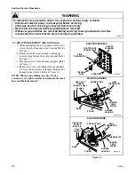
a. While supporting the access panel, remove two

screws from bottom edge of access panel. Refer
to Figure 7.

b. Gently lower the access panel to disengage

locators from bottom edge of front panel. Refer
to Figure 37.

c. Remove two screws holding bottom tabs on

front panel to dryer side panels. Refer to
Figure 37Swing bottom of front panel away
from dryer far enough to disengage hold-down
clips and locators from cabinet top.

d. Disconnect wires from door switch. Refer to

Figure 36.

NOTE: Refer to wiring diagram when rewiring
switch.

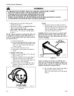
e. Disengage belt from motor and idler pulleys.

Refer to Figure 47.

NOTE: When reinstalling belt, be sure belt is
properly installed on motor and idler pulleys, and is
on the correct side of the idler lever. Refer to
Figure 47
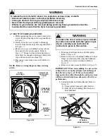
. Belt must be positioned around center
section of cylinder approximately three inches
ahead of rear rib on cylinder, with the ribbed
surface of the belt against the cylinder. Refer to
Figure 57
. After installing belt, manually rotate
cylinder counterclockwise to check that belt is
properly aligned.

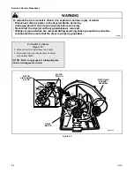
f. Remove four screws holding bulkhead to front

flange of cabinet. Then lift complete bulkhead
assembly out of slots in cabinet. Refer to
Figure 53.

IMPORTANT: When reassembling, be sure seal on
exhaust fan cover makes airtight seal on flange of
duct. Refer to Figure 44
If the seal is installed
improperly, the airflow through the exhaust system
will be restricted which can adversely affect dryer
performance.

g. Remove two cabinet top hold-down screws.

Refer to Figure 53.

h. Carefully remove cylinder out through front of

dryer.

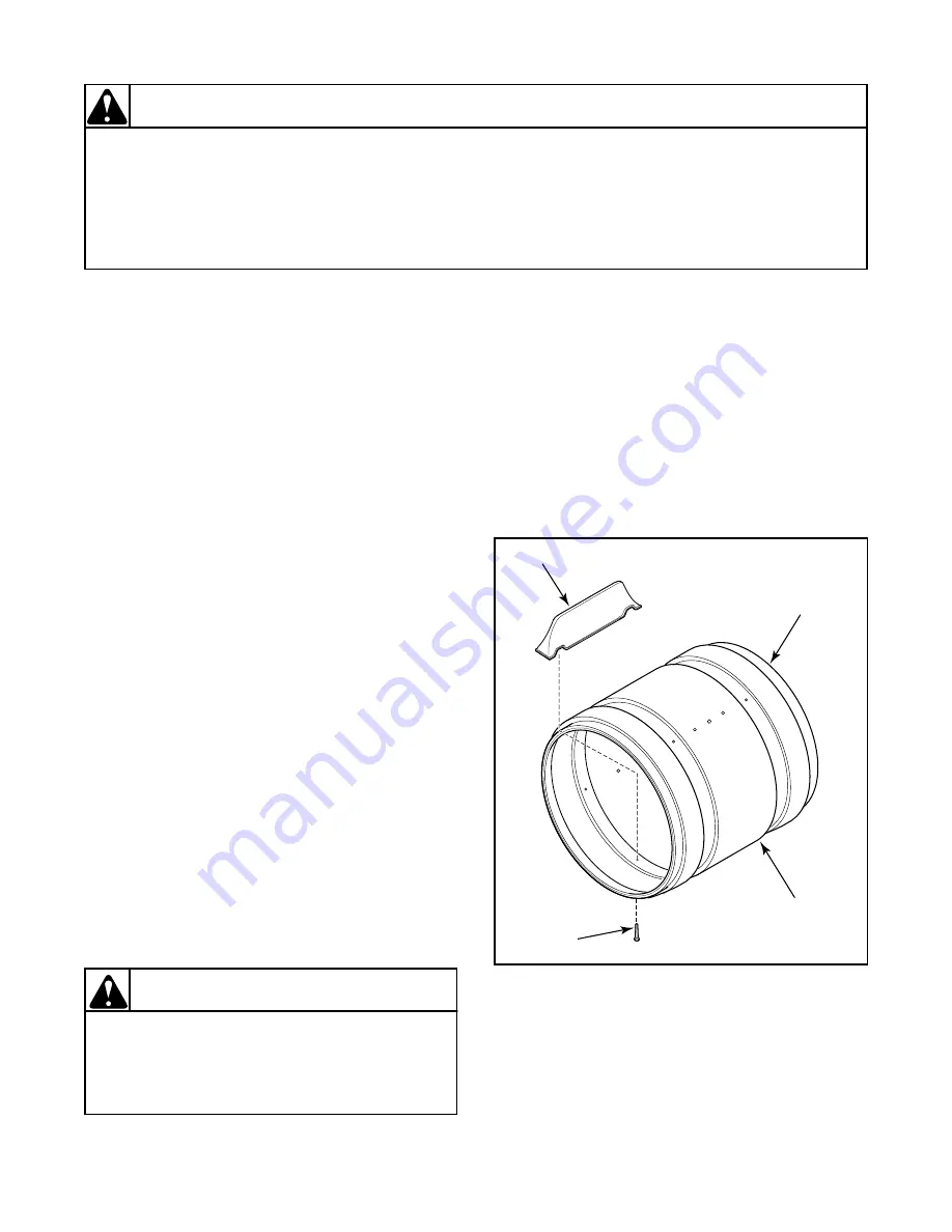
i. Baffles – Remove screws holding baffles to

cylinder. Refer to Figure 57.

To reduce the risk of serious injury or death
by carbon monoxide and other gases in gas
dryers, carefully read and follow all
instructions given in this section.

W005

WARNING

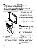
Figure 57

BAFFLE

CYLINDER

ASSEMBLY

(Includes

three baffles)

SCREW

REAR

RIB

D414SE1A

Summary of Contents for DAM 9

Page 1: ...DAM 9 SERVICE MANUAL INDUSTRIAL DRYERS PUBLICATION DATE 02 01 516514 ...

Page 2: ......

Page 3: ...net Top To Control Panel 20 17 Ground Wires From Rear Bulkhead To Timer Mounting Bracket and To Dryer Cabinet Top Ground Wires From Timer Mounting Bracket To Graphic Panel 21 18 Ground Wires From Dryer Base To Wire Harness and To Ignition Control Gas Models With Silicon nITRIDE Ignition System 21 Section 5 Service Procedures 19 Access Panel 23 20 Control Panel and Controls Metered and Nonmetered 2...

Page 4: ... SDE107 F1724 and SDE307 F1500 95 Model SDG409 F3058 96 Model SDE009 F3058 97 Model SDE407 F4350 98 Model SDE407 A3000 99 Model SDE107 F4350 100 Model SDE007 F4350 101 Model HDG709 F1102 102 Model HDG509 F1102 103 ModelS HDG109 F3000 SDG109 F3000 and SDG109 F5412 104 ModelS HDG109 F1102 and SDG109 F1124 105 Models HDG009 F3000 SDG009 F3000 and UDG009 F3000 106 Models HDG109 G3013 and SGG109 G3013 ...

Page 5: ...TANT and NOTE are followed by specific instructions IMPORTANT The word IMPORTANT is used to inform the reader of specific procedures where minor machine damage will occur if the procedure is not followed NOTE The word NOTE is used to communicate installation operation maintenance or servicing information that is important but not hazard related In the interest of safety some general precautions re...

Page 6: ...ms also recommends contacting an authorized technician and using authorized factory parts To reduce the risk of electric shock fire explosion serious injury or death Disconnect electric power to the dryer s before servicing Close gas shut off valve to gas dryer s before servicing Never start the dryer s with any guards panels removed Whenever ground wires are removed during servicing these ground ...

Page 7: ...rce from whom the machine was purchased or contact Alliance Laundry Systems at 920 748 3950 for the name and address of the nearest authorized parts distributor For technical assistance call 920 748 3121 Nameplate Location When calling or writing about your product be sure to mention model and serial numbers Model and serial numbers are located on nameplate s as shown D412P ...

Page 8: ...DE107 F1502 X X HDE107 F1702 X X HDE107 F3000 X X HDE107 G3003 X X X HDE107 G3018 X X HDE507 F1502 X X X X HDE507 F1702 X X X X HDE707 F1502 X X X HDE707 F1702 X X X HDEB07 J1502 X X X HDEB07 J1702 X X X HDEF07 J1502 X X X HDEF07 J1702 X X X HDG009 F1102 X X HDG009 F3000 X X HDG009 G3008 X X HDG109 F1102 X X HDG109 F3000 X X HDG109 G3013 X X HDG509 F1102 X X X X HDG709 F1102 X X X HDGB09 J1102 X X...

Page 9: ...X X X SDEB07 J1500 X X X SDEF07 J1500 X X X SDG009 F3000 X X SDG009 F3058 X X SDG109 F1124 X X X SDG109 F3000 X X SDG109 F3058 X X SDG109 F5412 X X SDG109 G3013 X X SDG409 F3058 X X X UDE007 F3000 X X UDE007 F3025 X X UDG009 F3000 X X UDG009 F3025 X X Dryer Model Nonmetered Model Metered Model Electronic Display Control Coin Slide Ready Coin Drop Ready Coin Drop Installed Card Reader Ready Card Re...

Page 10: ...ls room temperature air in through louvers at the rear of the dryer and over the heat source burner flame for gas and heating element for electric The heated air moves through the heater duct and into the cylinder where it circulates through the wet load The air then passes through the lint filter air duct and exhaust fan where it is vented to the outdoors D390SE3A LINT FILTER CYLINDER EXHAUST FAN...

Page 11: ...for electric models Loading door not closed Close door Inoperative door switch Test switch and replace if inoperative Timer improperly set Reset timer or try another cycle Inoperative timer Test timer and replace if inoperative Motor starting functions inoperative Doesn t start or motor just hums Check start switch and start windings Motor is dead will not run Check start switch start windings and...

Page 12: ... PROTECTOR POSSIBLE CAUSE TO CORRECT Incorrect Voltage See nameplate in door well for correct voltage Refer to Installation Instructions supplied with dryer for electrical requirements Clothes load too large Remove part of load A normal washer load is a normal dryer load Maximum load dryer cylinder one half full of wet clothes Clothes cylinder is binding Check cylinder for binding and out of round...

Page 13: ...ers for binding Check cylinder seals and glides for wear or damage Broken weak or disconnected idler lever spring Replace or reconnect spring Refer to Figure 48 Belt routed on wrong side of idler lever Reroute belt Refer to Figure 47 Oil on cylinder Wipe oil from cylinder Belt is inside out Reinstall belt with ribbed surface against cylinder Idler arm is binding Add grease between idler arm and mo...

Page 14: ...operly set set ina cool down period or a no heat cycle Reset timer Try another cycle Inoperative limit thermostat Test thermostat and replace if inoperative Inoperative drive motor switch Test switch and replace if inoperative Electric Models Inoperative heater assembly Test heater assembly and replace if cold Ohms do not read between 9 and 10 5 Ohms Electric Models Inoperative thermal fuse Test t...

Page 15: ...oken or open Replace igniter POSSIBLE CAUSE TO CORRECT Improper or inadequate exhaust system Weather hood flapper restricted See Installation Instructions supplied with dryer for exhaust requirements Burner heat not holding sensor contacts open Replace sensor or correct gas supply problem Insufficient gas supply Check gas supply and pressure Make sure gas shut off valve is turned on Cracked ignite...

Page 16: ...eater element heats or burner ignites when jumper wire is connected refer to Paragraph 10 Gas models Sensor contact closing Replace sensor Paragraph 42 step d or adjust burner flame Refer to Paragraph 59 Inoperative cycling thermostat Test thermostat and replace if inoperative Inoperative timer Test timer and replace if inoperative Broken loose or incorrect wiring Refer to wiring diagram POSSIBLE ...

Page 17: ...y and check for short POSSIBLE CAUSE TO CORRECT Heater assembly does not heat or burner does not ignite Refer to Paragraph 5 Too much water in articles being dried Remove excess water Laundry load too large Remove part of load A normal washer load is a normal dryer load Maximum load Dryer cylinder one half full of wet clothes Laundry load too small Add one or two bath towels to load Excessive lint...

Page 18: ... or inadequate exhaust system Refer to Installation Instructions supplied with dryer for exhaust requirements Clothes are removed from dryer before cycle has completed Allow the dryer to complete the cycle through the cool down to the OFF position Inoperative cycling thermostat Inoperative thermostat heater on the DELICATE setting Test cycling thermostat and replace if inoperative Inoperative time...

Page 19: ...wing FLASH CODE POSSIBLE CAUSE TO CORRECT Constant Light Internal failure Reset dryer If condition persists then replace control One Flash Air in gas line Purge air from gas line Sensor coated with Aluminum Oxide Wipe sensor clean or replace sensor if necessary Incorrect gas pressure Check for correct gas pressure If gas pressure is incorrect then contact local gas company Gas shut off valve close...

Page 20: ...ntrol module for secure connections Sensor and or appliance not properly grounded Check grounding from control to base and from lead in cord to dryer Rapid Flashing Incorrect frequency Contact a professional electrician to check the frequency and correct any problems Power supply must be 50 60 Hz 2 wire plus grounding earth wire Figure 1 WR WHITE ROGERS DIV EMERSON ELECTRIC CO DISCONNECT POWER BEF...

Page 21: ... HDE107 F1702 HDE107 G3003 HDE507 F1502 HDE507 F1702 HDE707 F1502 HDE707 F1702 HDEB07 J1502 HDEB07 J1702 HDEF07 J1502 HDEF07 1702 HDG009 F1102 HDG109 F1102 HDG509 F1102 HDG709 F1102 HDGB09 J1102 HDGF09 J1102 SDE007 F1500 SDE107 F1500 SDE107 F1724 SDE307 F1500 SDE407 F1500 SDE507 F1500 SDE607 F1500 SDE707 F1500 SDEA07 J1500 SDEB07 J1500 SDEF07 J1500 SDG109 F1124 UDE007 F3000 UDG009 F3000 Add Letter...

Page 22: ... Whenever ground wires are removed during servicing these ground wires must be reconnected to ensure that the dryer is properly grounded W001R1 WARNING Copyright Alliance Laundry Systems LLC DO NOT COPY or TRANSMIT 16 METERED AND NONMETERED MODELS GROUND WIRES FROM REAR BULKHEAD TO ACCUMULATOR BRACKET OR TIMER DEPENDING ON MODEL AND FROM CABINET TOP TO CONTROL PANEL Figure 4 Figure 4 D098GE3C GROU...

Page 23: ... TIMER MOUNTING BRACKET TO GRAPHIC PANEL Figure 5 18 GROUND WIRES FROM DRYER BASE TO WIRE HARNESS AND TO IGNITION CONTROL GAS MODELS WITH SILICON NITRIDE IGNITION SYSTEM Figure 6 Figure 5 GROUND WIRES D277SE3C Figure 6 WR WR WHITE ROGERS DIV EMERSON ELECTRIC CO DISCONNECT POWER BEFORE SERVICING DISCONNECT POWER BEFORE SERVICING DISCONNECT POWER BEFORE SERVICING DISCONNECT POWER BEFORE SERVICING DI...

Page 24: ...22 516514 Section 4 Grounding Copyright Alliance Laundry Systems LLC DO NOT COPY or TRANSMIT Notes ...

Page 25: ...ND CONTROLS METERED AND NONMETERED Figure 8 a Remove two control panel attaching screws and lay panel face down on protective padding on cabinet top b Disconnect all wires to fabric selector switch push to start switch and indicator light and remove ground clip and screw holding ground wire to cabinet top and control panel NOTE Refer to wiring diagram when reconnecting wires c Loosen setscrew hold...

Page 26: ...HOOD AND CONTROLS METERED AND NONMETERED MODELS D310PE3A CONTROL HOOD CONTROL HOOD REAR COVER LOCKWASHER LOCKWASHER FABRIC SELECTOR SWITCH CAP SCREW INDICATOR LIGHT SCREW SET SCREW SCREW CONTROL PANEL AND BRACKET ASSEMBLY PUSH TO START SWITCH ASSEMBLY SWITCH KNOB ASSEMBLY KEPS NUT GRAPHIC OVERLAY CABINET TOP KNURLED NUT HEX NUT SCREW ...

Page 27: ...h Refer to Figure 8 4 Remove hex nut from push to start switch 5 Disconnect wires from switches and indicator lights NOTE Refer to wiring diagram when rewiring switches and indicator light 6 Remove control panel overlay by peeling it from control panel frame NOTE Control panel overlay has an adhesive backing b Installation NOTE Before removing protective backing from new overlay check fit of overl...

Page 28: ...om ground terminal on timer Refer to Figure 4 f Disconnect wires from timer NOTE Refer to wiring diagram when rewiring timer g Remove two screws holding timer to plate Refer to Figure 9 To Test Timer Contacts Nonmetered Models Figure 4 1 Disconnect wires from timer except timer motor wires NOTE Refer to appropriate wiring diagram when rewiring timer 2 Manually rotate timer out of OFF position and ...

Page 29: ...LC DO NOT COPY or TRANSMIT Figure 9 NONMETERED TIMER DRYING TIM E OFF 15 30 45 60 75 90 105 D441P TIMER KNOB ASSEMBLY TIMER PLATE ASSEMBLY TIMER KEPS NUT CONTROL HOOD LOCKWASHER CAP SCREW TIMER CASE INSTRUCTION STICKER LOCKWASHER SCREW SET SCREW CABINET TOP SCREW CARRIAGE BOLT ...

Page 30: ...rnal rib at top of meter case NOTE When reinstalling service door front end of door must be inserted at about a 45 angle in order to engage notched tabs with internal rib at top of meter case c Remove right mounting screw and slide accumulator bracket back Once left mounting screw is over the keyhole opening pull accumulator bracket up and out of meter case NOTE When reinstalling accumulator brack...

Page 31: ...Models Figure 11 NOTE Refer to appropriate wiring diagram when rewiring switches 1 Set meter to read Ohms and apply leads on terminals of each switch You should read the following Switch A zero Ohms closed Switch B zero Ohms closed Switch C if present infinite open 2 Manually advance timing cam until it engages with ratchet wheel and the first click is heard Switch B should now read infinite open ...

Page 32: ...ist strap is not available touch dryer while it is plugged in before handling control to dissipate any charge NOTE New control is supplied in special anti static packaging material While holding control by its metal edges remove control from packaging material a Remove two control panel attaching screws Lay control panel assembly face down on protective padding b Press in on locking tabs and unplu...

Page 33: ...undry Systems LLC DO NOT COPY or TRANSMIT Figure 12 CONTROL PANEL CONTROL HOOD AND CONTROLS ELECTRONIC CONTROL MODELS D340PE3B CONTROL AND SHIELD CONTROL PANEL SCREW SCREW CONTROL HOOD CONTROL HOOD REAR PANEL LOCKWASHER NUT CAP SCREW SCREW GRAPHIC OVERLAY SCREW ...

Page 34: ...case 2 Disconnect wire harness from coin drawer switch and disconnect coin drop at disconnect plugs 3 Press in on locking tabs of service door switch and remove switch from bracket on meter case as shown in Figure 13 4 Use a 7 16 inch socket with No 310P4 1 4 inch Ratchet Extension Tool and remove two locknuts holding coin drop to front of meter case Refer to Figure 14 5 Lift back end of coin drop...

Page 35: ... coin drawer switch and disconnect coin drops at disconnect plugs 3 Press in on locking tabs of service door switch and remove switch from bracket on meter case as shown in Figure 15 4 Remove wire harness from multiplier Figure 16 Move wire harness out of the way 5 Remove multiplier from inside meter case Refer to Figure 16 NOTE Multiplier is held inside meter case by two Velcro strips 6 Press in ...

Page 36: ...lls behind the coin drawer housing Refer to Figure 17 9 Lift up back end of coin drop until the two coin return stops slide down past the coin drawer housing as shown in Figure 18 10 While holding back end of drop allow drop s front face plate to rest on bottom of meter case Refer to Figure 18 11 Carefully lift complete coin drop straight up and out of meter case Refer to Figure 19 NOTE When lifti...

Page 37: ...ousing as shown in Figure 22 4 Grasp top of coin drop front face plate between the two drops as shown in Figure 21 5 Lift up front face plate of coin drop with one hand while gently pushing down rear of drop with other hand so the bottom of the drop s front face plate clears coin drawer housing Refer to Figure 23 6 Carefully slide coin drop forward into position as shown in Figure 24 Front face pl...

Page 38: ...ng these ground wires must be reconnected to ensure that the dryer is properly grounded W001R1 WARNING Copyright Alliance Laundry Systems LLC DO NOT COPY or TRANSMIT 11 Reinstall multiplier and reconnect wires Refer to Figure 16 12 Close and lock service door Figure 23 Figure 24 W416SE1B REAR OF COIN DROP COIN DRAWER HOUSING COIN DROP FRONT FACE PLATE W417SE1B COIN DROP FRONT FACE PLATE FRONT PLAT...

Page 39: ...mately 45 off meter case to disengage notched tabs with internal rib at top of meter case Refer to Figure 10 NOTE When reinstalling service door front end of door must be inserted at about 45 angle in order to engage notched tabs with internal rib at top of meter case e Disconnect wires from accumulator Refer to Figure 10 NOTE Refer to wiring diagram when reconnecting wires f Remove ground screw h...

Page 40: ...re 28 NOTE Accumulator and hardware must be removed prior to raising cabinet top to a vertical position Refer to Figure 10 m Remove two cabinet top hold down screws Refer to Figure 28 n Lift cabinet top to a vertical position by hinging it on the rear hold down brackets Refer to Figure 29 Figure 29 NOTE While servicing cabinet top may be raised and hinged on the rear hold down brackets or supporte...

Page 41: ...er NOTE Refer to wiring diagram when rewiring timer g Remove cap screw lockwashers and nut holding timer case to control hood Refer to Figure 9 h While supporting the access panel remove two screws from bottom edge of access panel Refer to Figure 7 i Gently lower the access panel to disengage locators from bottom edge of front panel Refer to Figure 37 j Remove two screws holding bottom tabs on fro...

Page 42: ...eader 8 Remove cap screw lockwashers and nut holding security case to control hood Refer to Figure 30 9 While supporting the access panel remove two screws from bottom edge of access panel Refer to Figure 7 10 Gently lower the access panel to disengage locators from bottom edge of front panel 11 Remove two screws holding bottom tabs on front panel to dryer cabinet Refer to Figure 26 Swing front pa...

Page 43: ... Systems LLC DO NOT COPY or TRANSMIT Figure 30 SECURITY CASE AND CARD READER D307PE3A SCREW SERVICE DOOR BRACKET RETAINER NUT LOCKWASHER LOCKNUT LOCKNUT CARRIAGE BOLT SCREW CAP SCREW SECURITY CASE GASKET CONTROL HOOD CABINET TOP SHIELD CARD READER SCREW INSTRUCTIONS ...

Page 44: ...42 516514 Section 5 Service Procedures Copyright Alliance Laundry Systems LLC DO NOT COPY or TRANSMIT Figure 31 DRY519S CARDREADER ASSEMBLY CONTROL PANEL SCREW ...

Page 45: ... 30 CABINET TOP Nonmetered Models a Remove two control panel attaching screws and lay panel face down on protective padding on cabinet top Refer to Figure 8 b Disconnect all wires to components and remove ground clip and screw holding ground wire to cabinet top and control panel Refer to Figure 4 NOTE Refer to wiring diagram when reconnecting wires c Remove four screws holding timer and plate to t...

Page 46: ... When reinstalling accumulator bracket push it completely forward before replacing the right mounting screw f Disconnect wires from accumulator Refer to Figure 10 NOTE Refer to wiring diagram when reconnecting wires g Remove hex head ground screw holding green ground wire to accumulator mounting bracket Refer to Figure 10 h Remove two cap screws inside meter case holding meter case to cabinet top ...

Page 47: ...stems LLC DO NOT COPY or TRANSMIT 32 LINT FILTER Figure 32 a Open loading door and remove screw from end of lint filter b Lift lint filter out of air duct paying close attention to orientation IMPORTANT When installing lint filter be sure to install the filter with the words facing the front of the dryer If filter is installed backwards lint will accumulate in exhaust system which can adversely af...

Page 48: ...e all nine screws Pull bottom of door liner out then pull down removing door liner from door panel Remove four hinge attaching screws Remove door strike from door liner and reinstall on opposite side Insert liner under flange on bottom of door then push top of door liner into place Rotate door panel 180 degrees as shown Using a screwdriver remove two door plugs and reinstall on opposite side of do...

Page 49: ...NELS AND DOOR PULL a Remove four screws holding door assembly to hinges Refer to Figure 32 b Remove remaining screws around the door perimeter and separate panels Refer to Figure 34 c Remove wedge located behind door pull by carefully prying up on center of wedge Refer to Figure 34 d Remove door pull Refer to Figure 34 35 DOOR STRIKE Figure 34 a Open loading door b Remove screw holding door strike...

Page 50: ... Laundry Systems LLC DO NOT COPY or TRANSMIT 36 DOOR SEAL a Remove inner door panel from outer door panel Refer to Paragraph 34 b Grasp either end of door seal at bottom of door and remove seal from tabs on inner door panel by gently pulling on the seal Refer to Figure 35 NOTE When replacing seal be sure seal is not stretched or distorted The tab in the seal should be installed in each slot of the...

Page 51: ...wo screws from bottom edge of access panel Refer to Figure 7 b Gently lower the access panel to disengage locators from bottom edge of front panel Refer to Figure 37 c Remove two screws holding tabs on front panel to dryer side panels Swing bottom of front panel away from dryer far enough to disengage hold down clips and locators from cabinet top d Disconnect wires from door switch Refer to Figure...

Page 52: ...yright Alliance Laundry Systems LLC DO NOT COPY or TRANSMIT Figure 37 SCREW SCREW NAMEPLATE STICKER DOOR CATCH SCREW FRONT PANEL ACCESS PANEL DOOR CATCH HINGE HOLE PLUGS LOCATOR HOLD DOWN CLIP DOOR SWITCH FRONT PANEL SEAL SCREW LOCATOR D288PE3B ...

Page 53: ...emove four screws holding hinges to front panel 41 HOLD DOWN CLIPS AND LOCATORS a While supporting the access panel remove two screws from bottom edge of access panel Refer to Figure 7 b Gently lower the access panel to disengage locators from bottom edge of front panel Refer to Figure 37 c Remove two screws holding bottom tabs on front panel to dryer side panels Swing bottom edge of front panel a...

Page 54: ... be replaced individually b Burner Tube Igniter and Bracket NOTE Burner tube and igniter can be removed without removing gas valve and bracket 1 Remove one screw from right side of burner housing holding burner tube in place Refer to Figure 41 2 Gently move burner tube toward rear of dryer to disengage tab from slot on left side of burner housing Refer to Figure 39 3 Carefully rotate burner tube a...

Page 55: ...UD SENSOR TERMINALS TAB UNION NUT NIPPLE GAS VALVE HOLDING AND BOOSTER COIL SECONDARY COIL IGNITER WIRES DISCONNECT BLOCK BURNER TUBE SCREW BURNER HOUSING SENSOR ATTACHING SCREW SCREW SHUT OFF VALVE Shown in closed position D241SE3F IGNITION CONTROL BRACKET LEAD IN PIPE HEATER BOX ATTACHING SCREWS HEAT SHROUD UNION NUT NIPPLE MAIN COIL REDUNDANT COIL IGNITER AND SENSOR ASSEMBLY DISCONNECT BLOCK BU...

Page 56: ... BOOSTER COIL SPLIT COIL VALVE 4 1 5 2 3 D267SE3B SENSOR SECONDARY COIL HOLDING COIL BOOSTER COIL IGNITER 120 VOLT 60 HERTZ ELECTRICAL SUPPLY LINE D268SE3A To Test Gas Valve Coils Gas Models 1 Remove disconnect blocks from gas valve coils 2 Set test meter to read Ohms and put meter probes to terminals shown in Figure 40 and in the following chart SILICON CARBIDE IGNITION Coil Tolerance Readings SI...

Page 57: ...he ground wire connection in 12 pin block connected to module and the ground screw in base of dryer 2 Meter should read zero Ohms If meter registers an Ohm reading in any amount check ground wire connection and replace as necessary To Test Electrical Circuit to Ignition System Gas Models 1 Close gas shut off valve Refer to Figure 38 2 Remove valve wire harness disconnect block from the holding and...

Page 58: ... ensure that the dryer is properly grounded W001R1 WARNING Copyright Alliance Laundry Systems LLC DO NOT COPY or TRANSMIT SILICON CARBIDE IGNITION SILICON NITRIDE IGNITION Figure 41 IGNITER AND BRACKET BURNER TUBE TAB BURNER TUBE AIR SHUTTER ATTACHING SCREW WHITE CERAMIC PORTION D242SE1A WR D345PE1A WIRE HARNESS IGNITION CONTROL COMBUSTION DUCT IGNITER AND SENSOR ASSEMBLY BRACKET GAS VALVE ASSEMBL...

Page 59: ...rclockwise so tab is at 8 o clock position g Move air shutter end of burner tube slightly to the right and CAREFULLY remove burner tube and igniter assembly out through front of dryer IMPORTANT The igniter is very fragile Be careful not to damage it during removal h Remove screw holding burner housing to heat shroud Refer to Figure 39 i Remove screw holding front of burner housing to dryer base an...

Page 60: ...to Figure 7 b Gently lower the access panel to disengage locators from bottom edge of front panel Refer to Figure 37 c Disconnect wires from element and plate Refer to Figure 43 d Remove two screws holding element and plate to heater box and remove element and plate out through front of dryer Refer to Figure 43 NOTE When reassembling be sure all wire connectors are tight on element terminals therm...

Page 61: ...ess panel Refer to Figure 7 b Gently lower the access panel to disengage locators from bottom edge of front panel Refer to Figure 37 c Disconnect wires and remove thermostat or thermistor attaching screws Refer to Figure 44 Figure 44 ATTACHING SCREWS SEAL THERMISTOR OR THERMOSTAT GROUND SCREW WIRE HARNESS D400SE1A GROUND WIRE Figure 45 D409SE1A FRONT PANEL ATTACHING SCREW To Test Thermal Fuse Elec...

Page 62: ...Y a While supporting the access panel remove two screws from bottom edge of access panel Refer to Figure 7 b Gently lower the access panel to disengage locators from bottom edge of front panel Refer to Figure 37 c Remove three screws holding air duct to front bulkhead and remove air duct Refer to Figure 45 d Disconnect wires from thermostat or thermistor then disconnect ground wire screw NOTE Refe...

Page 63: ...es airtight seal on flange of duct Refer to Figure 44 If the seal is installed improperly the airflow through the exhaust system will be restricted which can adversely affect dryer performance IMPORTANT When reinstalling motor and exhaust assembly be sure wire harness on right side is clipped to motor mounting bracket and is routed along dryer base between motor mounting bracket and right side of ...

Page 64: ...then idler arm bolt is too tight 3 Loosen idler arm bolt 1 4 turn 4 Add grease between idler arm and motor mount k Impeller and housing 1 Remove screws holding cover to housing Refer to Figure 46 2 Hold motor pulley securely and unthread impeller from motor shaft right hand thread Use a 7 8 inch 6 point socket to aid in the removal of the impeller 3 Remove three screws holding the exhaust housing ...

Page 65: ...on the motor should be engaged with the anti rotating notch in the motor bracket m Motor Connection Block Terminals Remove terminals from the motor wire harness connection block using No 283P4 Terminal Extractor Tool as follows 1 Insert the tool into the block on the back of the terminal being removed Refer to Figure 51 2 Apply tool pressure to compress the terminal locking tab on terminal and for...

Page 66: ...es are removed during servicing these ground wires must be reconnected to ensure that the dryer is properly grounded W001R1 WARNING Copyright Alliance Laundry Systems LLC DO NOT COPY or TRANSMIT To Test Drive Motor Figure 52 1 Remove motor and exhaust assembly 2 Disconnect motor wire harness at motor disconnect block NOTE Refer to appropriate wiring diagram when rewiring motor switch Figure 52 2 6...

Page 67: ...tor connection block before starting this test Disconnect electric power to dryer before performing any of the following steps or when replacing inoperative motor switch W260 WARNING B Manually depress actuator Continuity broken between switch terminal 5 and black wire C Continuity broken between switch terminal 6 and yellow wire D Manually depress actuator Continuity exists between switch termina...

Page 68: ...right Alliance Laundry Systems LLC DO NOT COPY or TRANSMIT o Motor Windings Refer to SECTION 7 for Internal Wiring of the Dryer Motor Switch G 1 2 Ohms between black wire and orange wire Start Winding H 1 2 Ohms between yellow wire and orange wire I Continuity exists between orange wire and brown wire All motor windings check O K Run Main Winding Protector NO YES NO NO YES YES Inoperative start wi...

Page 69: ...d Disconnect wires from door switch Refer to Figure 36 NOTE Refer to wiring diagram when rewiring switch e Disengage belt from motor and idler pulley Refer to Figure 47 f Remove four screws holding bulkhead to front flange of cabinet and lift complete bulkhead assembly out of slots in cabinet Refer to Figure 53 g Remove air duct assembly Refer to Figure 53 IMPORTANT When reassembling be sure seal ...

Page 70: ...yright Alliance Laundry Systems LLC DO NOT COPY or TRANSMIT i Front Cylinder Seal Figure 55 When installing the cylinder seal it is important to remember these two steps 1 The stitching on the seal must face towards center of dryer 2 The short flap must be glued to the bulkhead and the long flap left loose IMPORTANT The replacement seal can be adhered to the bulkhead using No 22506P Sealant This i...

Page 71: ...NOTE Refer to wiring diagram when rewiring switch e Disengage belt from motor and idler pulleys Refer to Figure 47 f Remove four screws holding bulkhead to front flange of cabinet Then lift complete bulkhead assembly out of slots in cabinet Refer to Figure 53 IMPORTANT When reassembling be sure seal on exhaust fan cover makes airtight seal on flange of duct Refer to Figure 44 If the seal is instal...

Page 72: ...igure 47 NOTE When reinstalling belt be sure belt is properly installed on motor and idler pulleys and is on the correct side of the idler lever Refer to Figure 47 Belt must be positioned around center section of cylinder approximately three inches ahead of rear rib on cylinder with the ribbed surface of the belt against the cylinder Refer to Figure 57 After installing belt manually rotate cylinde...

Page 73: ...nd idler pulleys and is on the correct side of the idler pulleys Refer to Figure 47 Belt must be positioned around center section of cylinder approximately three inches ahead of rear rib on cylinder with the ribbed surface of the belt against cylinder Refer to Figure 57 After installing belt manually rotate cylinder counterclockwise to check that belt is properly aligned h Remove four screws holdi...

Page 74: ...dures Copyright Alliance Laundry Systems LLC DO NOT COPY or TRANSMIT Figure 58 REAR BULKHEAD ATTACHING SCREWS REAR BULKHEAD ATTACHING SCREWS CYLINDER ROLLER CYLINDER ROLLER HEATER BOX EXHAUST DUCT SCREW OUTLET COVER REAR SEAL D405SE3A ...

Page 75: ...h e Disengage belt from motor and idler pulleys Refer to Figure 47 f Remove four screws holding bulkhead to front flange of cabinet Then lift complete bulkhead assembly out of slots in cabinet Refer to Figure 53 IMPORTANT When reassembling be sure seal on exhaust fan cover makes airtight seal on flange of duct Refer to Figure 44 If the seal is installed improperly the airflow through the exhaust s...

Page 76: ... out of slots in cabinet Refer to Figure 53 IMPORTANT When reassembling be sure seal on exhaust fan cover makes airtight seal on flange of duct Refer to Figure 44 If the seal is installed improperly the airflow through the exhaust system will be restricted which can adversely affect dryer performance g Remove two cabinet top hold down screws Refer to Figure 28 h Carefully remove cylinder out throu...

Page 77: ...ystems LLC DO NOT COPY or TRANSMIT j Electric Models 1 Remove two screws holding element and plate to heater box then pull element down and away from heater box Refer to Figure 43 2 Remove all wires from terminal block Refer to appropriate wiring diagram when rewiring terminal block 3 Remove screw holding terminal block to rear bulkhead Refer to Figure 61 4 While supporting bulkhead remove the fou...

Page 78: ...rom bottom edge of front panel Refer to Figure 37 3 Remove two screws holding bottom tabs on front panel to dryer side panels Refer to Figure 37 Swing bottom of front panel away from dryer far enough to disengage hold down clips and locators from cabinet top 4 Disconnect wires from door switch Refer to Figure 36 NOTE Refer to wiring diagram when rewiring switch 5 Remove two cabinet top hold down s...

Page 79: ...ystems LLC DO NOT COPY or TRANSMIT b Power Cord 1 Remove access plate on rear of cabinet 2 Remove strain relief 3 Remove screw holding power cord ground wire to rear bulkhead Refer to Figure 62 NOTE Reinstall screw and ground wires into same hole in bulkhead when reinstalling power cord 4 Disconnect molex plug and remove power cord from rear of dryer cabinet NOTE A qualified electrician should che...

Page 80: ...ryer Refer to Figure 26 NOTE Air duct can remain attached to front bulkhead 7 Remove two cabinet top hold down screws Refer to Figure 26 8 Lift cabinet top to a vertical position by hinging it on the rear hold down brackets Refer to Figure 29 NOTE When servicing cabinet top may be raised and hinged on the rear hold down brackets or supported against wall behind dryer NOTE Retainer clips hold the w...

Page 81: ...he airflow through the dryer will be reduced which can cause fire and dryer malfunction 11 Remove thermostat Refer to Figure 43 12 Remove ground screw and green ground wire from wire harness and base of dryer Refer to Figure 44 13 Remove wires connecting wire harness to motor Refer to Figure 44 14 For Gas Models a Disconnect igniter wires at disconnect blocks sensor wires from sensor terminals Ref...

Page 82: ...igure 62 19 Remove two screws holding hold down brackets to back panel Refer to Figure 60 20 Remove 13 screws attaching back panel to dryer Refer to Figure 62 Remove back panel Metered Models a Side Panels 1 Remove two screws from bottom edge of access panel Refer to Figure 7 Remove access panel 2 Remove two screws holding bottom tabs on front panel to dryer cabinet front Refer to Figure 37 Swing ...

Page 83: ...ground screw holding green ground wire to accumulator mounting bracket Refer to Figure 10 12 Remove two screws and lockwashers holding accumulator to mounting bracket Remove accumulator 13 Remove two cabinet top hold down screws Refer to Figure 26 NOTE When servicing cabinet top may be raised and hinged on the rear hold down brackets or supported against wall behind dryer 14 Disconnect wires to co...

Page 84: ...ioned with flange inside the seal on exhaust fan cover Refer to Figure 44 If the duct or seal is installed improperly the airflow through the dryer will be reduced which can cause fire and dryer malfunction 8 Remove thermostat Refer to Figure 43 9 Remove ground screw and green ground wire from wire harness and base of dryer Refer to Figure 44 10 Remove wires connecting wire harness to motor Refer ...

Page 85: ...ove two screws from each rear cabinet top hold down bracket Refer to Figure 61 e Remove screw holding terminal block access plate to rear of dryer cabinet and remove plate f Remove wire harness clips g Remove locators and screws 12 Remove two cabinet top hold down screws Refer to Figure 26 NOTE When servicing cabinet top may be raised and hinged on the rear hold down brackets or supported against ...

Page 86: ...84 516514 Section 5 Service Procedures Copyright Alliance Laundry Systems LLC DO NOT COPY or TRANSMIT Figure 63 D420PE3A RIVET RIVETS RIVET SCREWS SCREWS SCREWS COIN METER BRACKET GUSSET ...

Page 87: ...ting the legs until dryer is level NOTE Legs can be adjusted outside the dryer by using a 1 1 4 inch size wrench or from inside the dryer with lower front access panel removed by using a 1 4 inch drive ratchet with extension b Keep dryer as close to the floor as possible All four legs must rest firmly on the floor so weight of the dryer is evenly distributed The dryer MUST NOT rock IMPORTANT DO NO...

Page 88: ... of front panel Refer to Figure 37 c Set timer at 60 minutes nonmetered or add coins metered d Close the loading door Start the dryer in a heat setting refer to Operating Instructions supplied with the dryer The dryer will start the igniter will glow red and the main burner will ignite e Allow the dryer to operate for approximately five minutes then loosen the air shutter lockscrew Refer to Figure...

Page 89: ...CON CARBIDE IGNITION SILICON NITRIDE IGNITION Figure 65 AIR SHUTTER LOCKSCREW AIR SHUTTER SHUT OFF VALVE HANDLE 1 8 PIPE PLUG For checking manifold pressure D265SE3A WR AIR SHUTTER LOCKSCREW AIR SHUTTER SHUT OFF VALVE HANDLE Shown in Open Position 1 8 PIPE PLUG For checking manifold pressure D363SE3A ...

Page 90: ...88 516514 Section 6 Adjustments Copyright Alliance Laundry Systems LLC DO NOT COPY or TRANSMIT Notes ...

Page 91: ...removed Whenever ground wires are removed during servicing these ground wires must be reconnected to ensure that the dryer is properly grounded W001R1 WARNING Copyright Alliance Laundry Systems LLC DO NOT COPY or TRANSMIT Section 7 Internal Wiring of Dryer Motor Switch Figure 66 R R S 2 6 4 3 5 1 MAIN START ORANGE CUSTOMER CIRCUIT OVERLOAD PROTECTOR BROWN BLACK YELLOW PUSH TO START LINE SWITCH SHO...

Page 92: ...90 516514 Section 7 Internal Wiring of Dryer Motor Switch Copyright Alliance Laundry Systems LLC DO NOT COPY or TRANSMIT Notes ...

Page 93: ...r s instructions may result in conditions which can produce bodily injury and or property damage W030 WARNING Copyright Alliance Laundry Systems LLC DO NOT COPY or TRANSMIT Section 8 Wiring Diagrams WIRING DIAGRAMS AND SCHEMATICS FOUND ON THE FOLLOWING PAGES ARE FOR MODELS COVERED IN THIS MANUAL ...

Page 94: ...maintain and or operate this machine according to the manufacturer s instructions may result in conditions which can produce bodily injury and or property damage W030 WARNING Copyright Alliance Laundry Systems LLC DO NOT COPY or TRANSMIT MODEL SDE707 F1500 ...

Page 95: ...maintain and or operate this machine according to the manufacturer s instructions may result in conditions which can produce bodily injury and or property damage W030 WARNING Copyright Alliance Laundry Systems LLC DO NOT COPY or TRANSMIT MODEL SDE607 F1500 ...

Page 96: ...and or operate this machine according to the manufacturer s instructions may result in conditions which can produce bodily injury and or property damage W030 WARNING Copyright Alliance Laundry Systems LLC DO NOT COPY or TRANSMIT MODELS SDE407 F1500 AND SDE507 F1500 ...

Page 97: ... operate this machine according to the manufacturer s instructions may result in conditions which can produce bodily injury and or property damage W030 WARNING Copyright Alliance Laundry Systems LLC DO NOT COPY or TRANSMIT MODELS SDE107 F1500 SDE107 F1724 AND SDE307 F1500 ...

Page 98: ...maintain and or operate this machine according to the manufacturer s instructions may result in conditions which can produce bodily injury and or property damage W030 WARNING Copyright Alliance Laundry Systems LLC DO NOT COPY or TRANSMIT MODEL SDG409 F3058 ...

Page 99: ...maintain and or operate this machine according to the manufacturer s instructions may result in conditions which can produce bodily injury and or property damage W030 WARNING Copyright Alliance Laundry Systems LLC DO NOT COPY or TRANSMIT MODEL SDE009 F3058 ...

Page 100: ...maintain and or operate this machine according to the manufacturer s instructions may result in conditions which can produce bodily injury and or property damage W030 WARNING Copyright Alliance Laundry Systems LLC DO NOT COPY or TRANSMIT MODEL SDE407 F4350 ...

Page 101: ...maintain and or operate this machine according to the manufacturer s instructions may result in conditions which can produce bodily injury and or property damage W030 WARNING Copyright Alliance Laundry Systems LLC DO NOT COPY or TRANSMIT MODEL SDE407 A3000 ...

Page 102: ... maintain and or operate this machine according to the manufacturer s instructions may result in conditions which can produce bodily injury and or property damage W030 WARNING Copyright Alliance Laundry Systems LLC DO NOT COPY or TRANSMIT MODEL SDE107 F4350 ...

Page 103: ... maintain and or operate this machine according to the manufacturer s instructions may result in conditions which can produce bodily injury and or property damage W030 WARNING Copyright Alliance Laundry Systems LLC DO NOT COPY or TRANSMIT MODEL SDE007 F4350 ...

Page 104: ... maintain and or operate this machine according to the manufacturer s instructions may result in conditions which can produce bodily injury and or property damage W030 WARNING Copyright Alliance Laundry Systems LLC DO NOT COPY or TRANSMIT MODEL HDG709 F1102 ...

Page 105: ... maintain and or operate this machine according to the manufacturer s instructions may result in conditions which can produce bodily injury and or property damage W030 WARNING Copyright Alliance Laundry Systems LLC DO NOT COPY or TRANSMIT MODEL HDG509 F1102 ...

Page 106: ... operate this machine according to the manufacturer s instructions may result in conditions which can produce bodily injury and or property damage W030 WARNING Copyright Alliance Laundry Systems LLC DO NOT COPY or TRANSMIT MODELS HDG109 F3000 SDG109 F3000 AND SDG109 F5412 ...

Page 107: ... and or operate this machine according to the manufacturer s instructions may result in conditions which can produce bodily injury and or property damage W030 WARNING Copyright Alliance Laundry Systems LLC DO NOT COPY or TRANSMIT MODELS HDG109 F1102 AND SDG109 F1124 ...

Page 108: ... operate this machine according to the manufacturer s instructions may result in conditions which can produce bodily injury and or property damage W030 WARNING Copyright Alliance Laundry Systems LLC DO NOT COPY or TRANSMIT MODELS HDG009 F3000 SDG009 F3000 AND UDG009 F3000 ...

Page 109: ... and or operate this machine according to the manufacturer s instructions may result in conditions which can produce bodily injury and or property damage W030 WARNING Copyright Alliance Laundry Systems LLC DO NOT COPY or TRANSMIT MODELS HDG109 G3013 AND SGG109 G3013 ...

Page 110: ... maintain and or operate this machine according to the manufacturer s instructions may result in conditions which can produce bodily injury and or property damage W030 WARNING Copyright Alliance Laundry Systems LLC DO NOT COPY or TRANSMIT MODEL HDG009 F1102 ...

Page 111: ... maintain and or operate this machine according to the manufacturer s instructions may result in conditions which can produce bodily injury and or property damage W030 WARNING Copyright Alliance Laundry Systems LLC DO NOT COPY or TRANSMIT MODEL HDG009 G3008 ...

Page 112: ... and or operate this machine according to the manufacturer s instructions may result in conditions which can produce bodily injury and or property damage W030 WARNING Copyright Alliance Laundry Systems LLC DO NOT COPY or TRANSMIT MODELS HDE707 F1502 AND HDE707 F1702 ...

Page 113: ... and or operate this machine according to the manufacturer s instructions may result in conditions which can produce bodily injury and or property damage W030 WARNING Copyright Alliance Laundry Systems LLC DO NOT COPY or TRANSMIT MODELS HDE507 F1502 AND HDE507 F1702 ...

Page 114: ... operate this machine according to the manufacturer s instructions may result in conditions which can produce bodily injury and or property damage W030 WARNING Copyright Alliance Laundry Systems LLC DO NOT COPY or TRANSMIT MODELS HDE107 F3000 SDE107 F3000 AND SDE107 F5412 ...

Page 115: ... and or operate this machine according to the manufacturer s instructions may result in conditions which can produce bodily injury and or property damage W030 WARNING Copyright Alliance Laundry Systems LLC DO NOT COPY or TRANSMIT MODELS HDE107 F1502 AND HDE107 F1702 ...

Page 116: ... operate this machine according to the manufacturer s instructions may result in conditions which can produce bodily injury and or property damage W030 WARNING Copyright Alliance Laundry Systems LLC DO NOT COPY or TRANSMIT MODELS HDE107 G3003 HDE107 G3018 AND SDE107 G3018 ...

Page 117: ... maintain and or operate this machine according to the manufacturer s instructions may result in conditions which can produce bodily injury and or property damage W030 WARNING Copyright Alliance Laundry Systems LLC DO NOT COPY or TRANSMIT MODEL HDE007 F1702 ...

Page 118: ... operate this machine according to the manufacturer s instructions may result in conditions which can produce bodily injury and or property damage W030 WARNING Copyright Alliance Laundry Systems LLC DO NOT COPY or TRANSMIT MODELS HDE007 F3000 SDE007 F3000 AND UDE007 F3000 ...

Page 119: ...te this machine according to the manufacturer s instructions may result in conditions which can produce bodily injury and or property damage W030 WARNING Copyright Alliance Laundry Systems LLC DO NOT COPY or TRANSMIT MODELS HDE007 G3003 HDE007 G3008 HDE007 G3010 AND SDE007 G3018 ...

Page 120: ... maintain and or operate this machine according to the manufacturer s instructions may result in conditions which can produce bodily injury and or property damage W030 WARNING Copyright Alliance Laundry Systems LLC DO NOT COPY or TRANSMIT MODEL UDE007 F3025 ...

Page 121: ... maintain and or operate this machine according to the manufacturer s instructions may result in conditions which can produce bodily injury and or property damage W030 WARNING Copyright Alliance Laundry Systems LLC DO NOT COPY or TRANSMIT MODEL UDG009 F3025 ...

Page 122: ...rding to the manufacturer s instructions may result in conditions which can produce bodily injury and or property damage W030 WARNING Copyright Alliance Laundry Systems LLC DO NOT COPY or TRANSMIT MODELS HDEB07 J1502 HDEB07 J1702 HDEF07 J1502 HDEF07 J1702 SDEA07 J1500 SDEB07 J1500 AND SDEF07 J1500 ...

Page 123: ... and or operate this machine according to the manufacturer s instructions may result in conditions which can produce bodily injury and or property damage W030 WARNING Copyright Alliance Laundry Systems LLC DO NOT COPY or TRANSMIT MODELS HDGB09 J1102 AND HDGF09 J1102 ...

Page 124: ... maintain and or operate this machine according to the manufacturer s instructions may result in conditions which can produce bodily injury and or property damage W030 WARNING Copyright Alliance Laundry Systems LLC DO NOT COPY or TRANSMIT MODEL SDEA07 J3000 ...

Page 125: ... maintain and or operate this machine according to the manufacturer s instructions may result in conditions which can produce bodily injury and or property damage W030 WARNING Copyright Alliance Laundry Systems LLC DO NOT COPY or TRANSMIT MODEL SDEA07 J4350 ...

Page 126: ...124 516514 Section 8 Wiring Diagrams Copyright Alliance Laundry Systems LLC DO NOT COPY or TRANSMIT Notes ...

Page 127: ......

Page 128: ......

Reviews: