Model No.
Main P.C. Board
Tools Needed: 1/4” Flat Blade Screwdriver
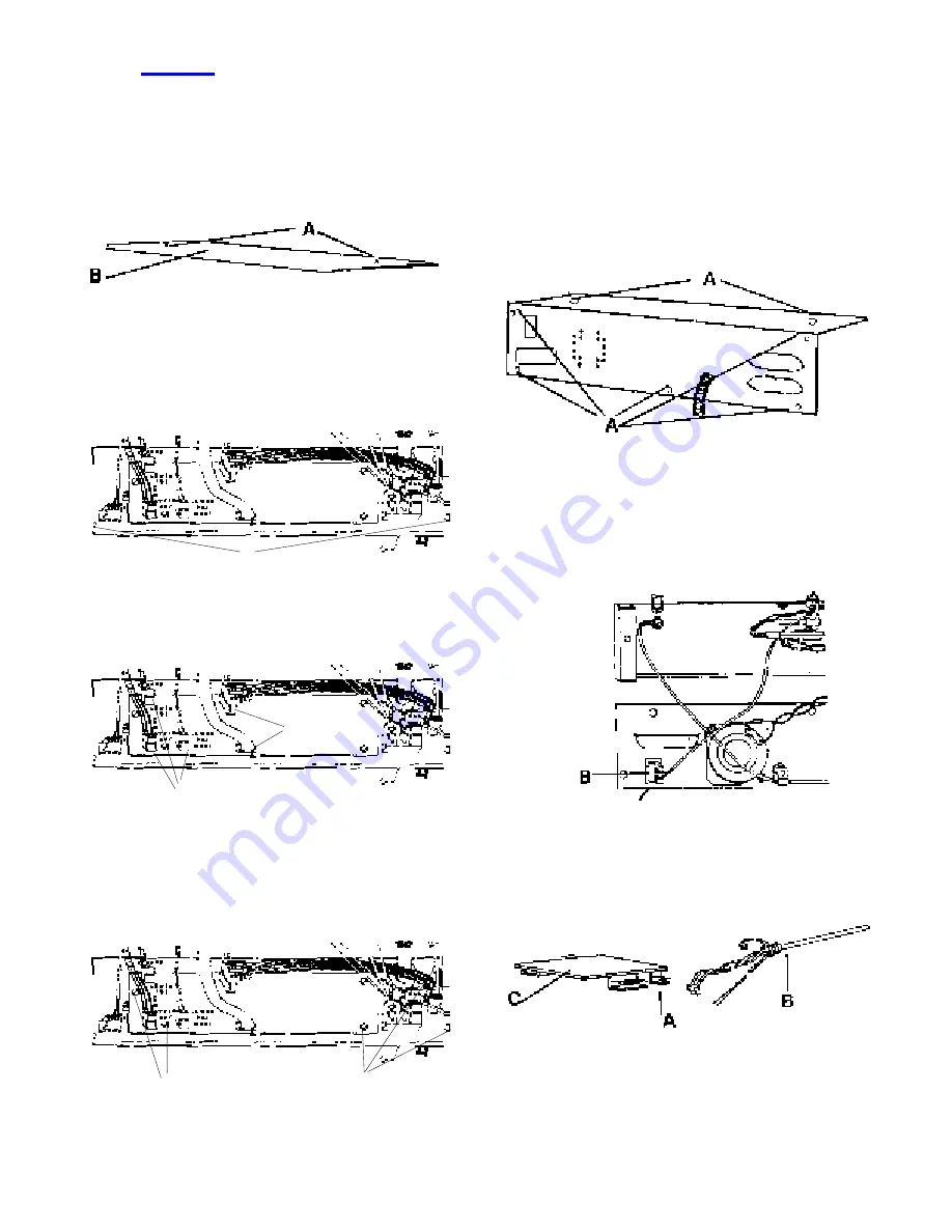
1. Disengage safety latch and lower toaster to toast
position. Using 1/4” flat blade screwdriver
remove (2) screws (A) from cover (B) on lower
control box, and remove cover. See figure 16.
2. Using the 1/4” flat blade screwdriver remove (2)
screws (A) from the front of the lower control box
and carefully pull back faceplate exposing main
P.C. Board. See figure 17.
3. Disconnect the (5) wire connectors (A) from the
board. See figure 18.
4. Using the 1/4” flat blade screwdriver remove the
(5) screws (A) from the front of the faceplate
which holds the board to the faceplate, and
remove the old board. See figure 19.
5. To install the new P.C. Board reverse steps 1-4.
Make sure all wire connections are tight.
Model No. 411-85S Probe Assembly
Tools Needed: 3/16” Flateblade Screwdriver
1/4” Flatblade Screwdriver
Nut Driver 8-32
1. Using the 1/4” flat blade screwdriver remove (7)
screws (A) that secure the cover tot he control
box. See figure 20.
2. Using a 3/16” flateblade screwdriver loosen the
(2) screws (A) that attach probe wires to the
yellow mini-jack (B) and remove the (2) wires
from this connection. See figure 21.
3. Unplug wire connector (A) from the probe (B) to
the printed circuit board (C). See figure 22.
figure 16
figure 17
A
A
A
figure 18
A
A
figure 19
figure 22
figure 21
figure 20
8
Summary of Contents for Excalibur 411-SL Series
Page 12: ...WIRING DIAGRAM 12...


