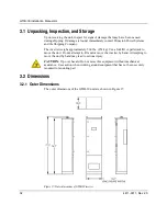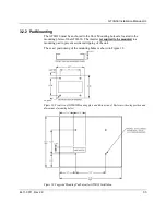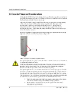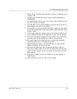
GTIB-30 Installation Manual-UL
4411-0011, Rev 2.0
27
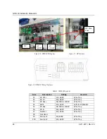
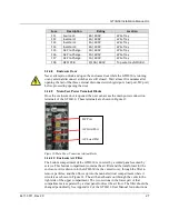
Fuse
Description
Rating
Location
F11
Source L3
4A / 600V
Wire Tray
F12
Inverter L1
4A / 600V
Wire Tray
F13
Inverter L2
4A / 600V
Wire Tray
F14
Inverter L3
4A / 600V
Wire Tray
F15
AC Pre-Charge
1A / 600V
Wire Tray
F16
AC Pre-Charge
1A / 600V
Wire Tray
F17
AC Pre-Charge
1A / 600V
Wire Tray
F18
GFDI PCB
3/10A / 600V
Top wire tray GFDI Bd
2.1.4.8
Enclosure Door
Never attempt to unlock and open the enclosure door while the GTIB-30 is running
or any external disconnect switches are still closed. Wait at least five minutes after
opening the last of the three external disconnect switch (grid port, load port, DC port)
before proceeding opening the door.
2.1.4.9
Main User Power Terminal Blocks
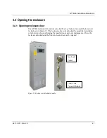
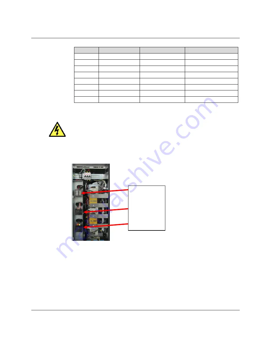
Once the enclosure door is opened, the user can access the main power connection
terminals of the GTIB-30. These terminals are shown in Figure 13.
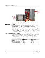
Figure 13: Main Power Connection terminal blocks
2.1.4.10
Enclosure Air Filter
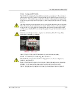
The bottom compartment of the GTIB-30 is covered by a vented panel secured by
screws. This bottom compartment contains the air filter and the transformer for the
enclosure. Air is drawn into the GTIB-30 via the vented cover, through the filter to
remove particles, and then flows up into the main electrical compartment where it
circulates as shown in Figure 14. The air then exhausts out through the vents in the
right side of the upper compartment. The two sections in the lower part of that
compartment are separated by a clear panel to direct the air flow. The filter should be
changed periodically. See Appendix C of the GTIB-30 User Manual for instructions.
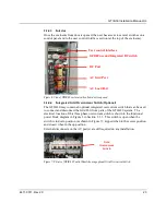
DC Port
AC Grid Port
AC Load Port
Summary of Contents for GTIB-30
Page 1: ...Clean power made simple GTIB 30 Installation Manual ...
Page 2: ...www princetonpower com 4411 0011 Rev 2 0 April 1st 2014 ...
Page 11: ...About this Manual 4411 0011 Rev 2 0 xi This page intentionally left blank ...
Page 15: ...Contents 4411 0011 Rev 2 0 15 This page intentionally left blank ...
Page 16: ...1 Introduction ...
Page 18: ...2 System Overview and Configurations ...
Page 31: ...3 Pre Installation ...
Page 36: ...GTIB 30 Installation Manual UL 36 4411 0011 Rev 2 0 This page intentionally left blank ...
Page 37: ...4 Wiring Instructions ...
Page 56: ...GTIB 30 Installation Manual UL 56 4411 0011 Rev 2 0 This page intentionally left blank ...
Page 57: ...5 Commissioning Sequences ...
Page 61: ...GTIB 30 Installation Manual UL 4411 0011 Rev 2 0 61 This page intentionally left blank ...
Page 62: ...A GTIB 30 kW Specifications ...
Page 65: ...GTIB 30 Installation Manual UL 4411 0011 Rev 2 0 65 This page intentionally left blank ...
Page 66: ...B Return Material Authorization Contact and Product Information ...
Page 69: ...GTIB 30 Installation Manual UL 4411 0011 Rev 2 0 69 This page intentionally left blank ...

