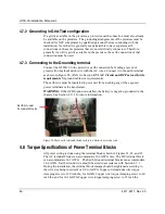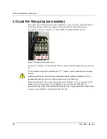
GTIB-30 Installation Manual-UL
4411-0011, Rev 2.0
33
3.2.2 Pad Mounting
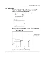
The GTIB-30 must be anchored to the floor. Mounting holes are located in the
mounting plates of the GTIB-30. The inverter
is required to be
mounted
to a
mounting pad to prevent accidental tipping of the unit.
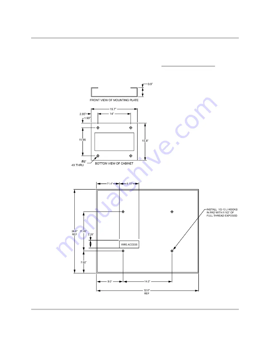
The exact positioning of the mounting holes is shown in Figure 18.
Figure 18: Front view of GTIB-30 Mounting plate and Bottom view of Enclosure (showing position and
dimensions of mounting holes).
Figure 19: Suggested Mounting Pad Layout for GTIB-30 Installation.
Summary of Contents for GTIB-30
Page 1: ...Clean power made simple GTIB 30 Installation Manual ...
Page 2: ...www princetonpower com 4411 0011 Rev 2 0 April 1st 2014 ...
Page 11: ...About this Manual 4411 0011 Rev 2 0 xi This page intentionally left blank ...
Page 15: ...Contents 4411 0011 Rev 2 0 15 This page intentionally left blank ...
Page 16: ...1 Introduction ...
Page 18: ...2 System Overview and Configurations ...
Page 31: ...3 Pre Installation ...
Page 36: ...GTIB 30 Installation Manual UL 36 4411 0011 Rev 2 0 This page intentionally left blank ...
Page 37: ...4 Wiring Instructions ...
Page 56: ...GTIB 30 Installation Manual UL 56 4411 0011 Rev 2 0 This page intentionally left blank ...
Page 57: ...5 Commissioning Sequences ...
Page 61: ...GTIB 30 Installation Manual UL 4411 0011 Rev 2 0 61 This page intentionally left blank ...
Page 62: ...A GTIB 30 kW Specifications ...
Page 65: ...GTIB 30 Installation Manual UL 4411 0011 Rev 2 0 65 This page intentionally left blank ...
Page 66: ...B Return Material Authorization Contact and Product Information ...
Page 69: ...GTIB 30 Installation Manual UL 4411 0011 Rev 2 0 69 This page intentionally left blank ...

