GTIB-30 Installation Manual-UL
40
4411-0011, Rev 2.0
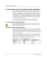
4.3 External disconnect and overcurrent protection requirements
For safe installation, operation and maintenance, it is required that external
disconnect switches and overcurrent devices be installed on all ports of the GTIB-30
(See Table 3 for required ratings). It is highly recommended that all disconnect
switches are installed in a single neat enclosure or bypass box in close proximity to
the GTIB-30 inverter. All switches inside the bypass-box should be appropriately
labeled and the necessary warning labels must be included. Circuit breakers can be
used as disconnect switches. These then provide both over current protection and
also function as disconnect switches.
DC disconnect switches must be used on the DC ports. External overcurrent
protection is required for Battery or PV operation. See Table 3 for ratings.
4.3.1 AC Disconnect switch requirements
The external disconnect switches on the utility grid and load port as well as any
bypass switches need to break all phases and leave the neutral unbroken to be fully
compliant with NEC requirements.
4.3.2 DC Disconnect switch requirements
The DC port (battery or PV) must be equipped with external two pole devices that
enable disconnection of the DC source or load. In most cases, the combiner box of
the PV array will provide this capability for the PV port. Many battery banks will
also provide a disconnect device in which case another external disconnect device on
the battery port is not needed.
If the GTIB-30 is equipped with the optional GFDI, the external disconnect must
only break the ungrounded conductor. If the GTIB-30 does not have the optional
GFDI or there is an external GFDI installed it is up to the contractor / installer to
decide how to wire the disconnect as to not defeat the GFDI circuit.
Table 3: AC and DC Overcurrent Protection Rating Requirements
Connection
GTIB-208-30
GTIB-480-30
Grid Port
100A
50A
Load Port (if installed)
100A
50A
DC Port
150A
150A
Summary of Contents for GTIB-30
Page 1: ...Clean power made simple GTIB 30 Installation Manual ...
Page 2: ...www princetonpower com 4411 0011 Rev 2 0 April 1st 2014 ...
Page 11: ...About this Manual 4411 0011 Rev 2 0 xi This page intentionally left blank ...
Page 15: ...Contents 4411 0011 Rev 2 0 15 This page intentionally left blank ...
Page 16: ...1 Introduction ...
Page 18: ...2 System Overview and Configurations ...
Page 31: ...3 Pre Installation ...
Page 36: ...GTIB 30 Installation Manual UL 36 4411 0011 Rev 2 0 This page intentionally left blank ...
Page 37: ...4 Wiring Instructions ...
Page 56: ...GTIB 30 Installation Manual UL 56 4411 0011 Rev 2 0 This page intentionally left blank ...
Page 57: ...5 Commissioning Sequences ...
Page 61: ...GTIB 30 Installation Manual UL 4411 0011 Rev 2 0 61 This page intentionally left blank ...
Page 62: ...A GTIB 30 kW Specifications ...
Page 65: ...GTIB 30 Installation Manual UL 4411 0011 Rev 2 0 65 This page intentionally left blank ...
Page 66: ...B Return Material Authorization Contact and Product Information ...
Page 69: ...GTIB 30 Installation Manual UL 4411 0011 Rev 2 0 69 This page intentionally left blank ...

