GTIB-30 Installation Manual-UL
4411-0011, Rev 2.0
49
4.11 DC Port Wiring
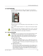
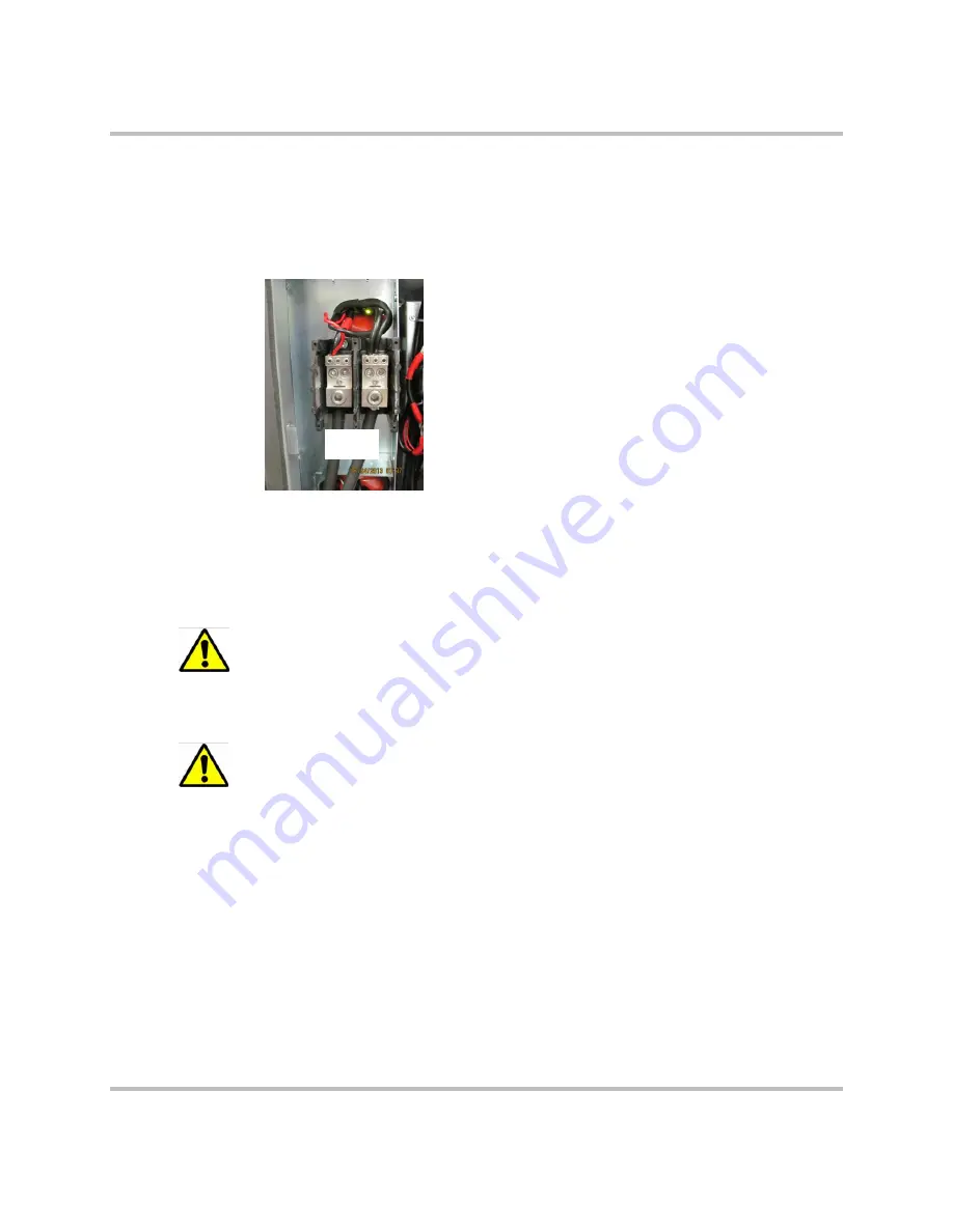
Run two wires that are rated in accordance with Section 4.5.1 from the Battery
disconnect or the PV combiner box to the
DC-
and
DC+
terminal blocks inside the
GTIB-30 as shown.
Figure 27: DC port wiring connections.
During the wiring all of the terminal block clamps should be tightened to 1.2-1.4 Nm
/ 10.6-12.4 lb.in.
Wires should be stripped a minimum of .55” (14mm) before inserting into terminal
blocks.
It is essential that the polarity of the Battery or the PV array be correct. Use a multi-
meter to check polarity if unsure. Ensure that Battery or PV array is disconnected
again after measurements before proceeding with installation.
4.11.1 DC Port grounding
WARNING:
For systems equipped with an optional integrated GFDI the (AC/DC
circuit) Ground Terminals must NOT be used to ground either the positive or
negative nodes of the input DC circuit. The GFDI circuit grounds the negative DC
terminal to earth ground, and no other ground may be used to ground either the
positive and negative nodes.
DC Input connects to a Battery:
If installing an ungrounded floating DC system, the GFDI option should not be
installed as part of the GTIB-30. When the GFDI option is not installed, it is up
to the installer to decide if the battery system should be floating, negative, center
or positive grounded.
DC input connects a PV array:
All PV array frames should be grounded appropriately. The grounding wire of
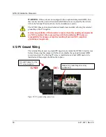
the PV frames should be done via the Earth Ground terminal shown in Figure 21.
Connecting the PV array power connection to a different ground point will
bypass the GFDI unit (if installed) in the GTIB-30 and is not recommended (see
section 4.12 PV Ground Wiring).
+ -
N
Summary of Contents for GTIB-30
Page 1: ...Clean power made simple GTIB 30 Installation Manual ...
Page 2: ...www princetonpower com 4411 0011 Rev 2 0 April 1st 2014 ...
Page 11: ...About this Manual 4411 0011 Rev 2 0 xi This page intentionally left blank ...
Page 15: ...Contents 4411 0011 Rev 2 0 15 This page intentionally left blank ...
Page 16: ...1 Introduction ...
Page 18: ...2 System Overview and Configurations ...
Page 31: ...3 Pre Installation ...
Page 36: ...GTIB 30 Installation Manual UL 36 4411 0011 Rev 2 0 This page intentionally left blank ...
Page 37: ...4 Wiring Instructions ...
Page 56: ...GTIB 30 Installation Manual UL 56 4411 0011 Rev 2 0 This page intentionally left blank ...
Page 57: ...5 Commissioning Sequences ...
Page 61: ...GTIB 30 Installation Manual UL 4411 0011 Rev 2 0 61 This page intentionally left blank ...
Page 62: ...A GTIB 30 kW Specifications ...
Page 65: ...GTIB 30 Installation Manual UL 4411 0011 Rev 2 0 65 This page intentionally left blank ...
Page 66: ...B Return Material Authorization Contact and Product Information ...
Page 69: ...GTIB 30 Installation Manual UL 4411 0011 Rev 2 0 69 This page intentionally left blank ...

