A3. CENTER OF GRAVITY
42
Basic Principles
Make the right start
–
know the load capacities of your
Truck Mounted Forklift. The rated capacity of the
machine is the weight that the machine is capable of
lifting under safe operating conditions. Remember that
the type of terrain or ground conditions can reduce the
amount you should lift.
The shape of the load will also affect the lift capacity of
the machine. Inspect the load you intend to lift. Make
sure that you know the weight of the load. If the weight
is not marked or shown on the load, check the weight
of the load with your supervisor or have it weighed. If it
is too heavy split the load and restack it. It is common
for a large capacity conventional forklift to be used
when loading trucks or trailers in a yard. Do not expect
the Truck Mounted Forklift to lift the load just because
a conventional yard forklift initially loaded it.
Remember that if attachments are used other than the
standard forks which are normally furnished with the
Truck Mounted Forklift, such attachments will reduce
the lifting capacity and affect other machine handling
characteristics.
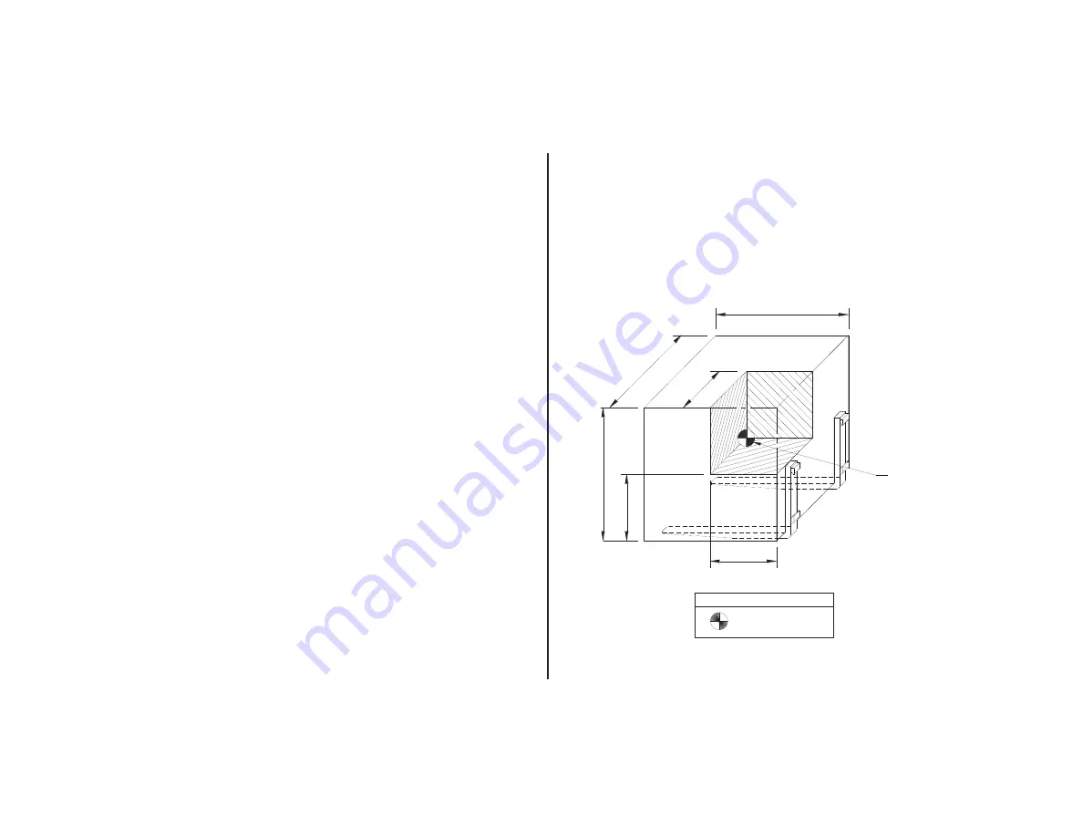
With the Truck Mounted Forklift, the rated capacity is
based on a cube measuring
48”
in all three dimensions
with the center of gravity in the center of this cube.
This is known as a
24”
load center. If the dimensions of
the load increase or the position of the center of gravity
or load moves forward, the lifting capacity of the
machine will be reduced.
2
4
"
4
8
"
48
"
24
"
= Center of Gravity
24"
KEY
48"
LOAD CENTER
24"
Summary of Contents for Truck Mounted Forklift
Page 2: ...25 1 16758 7 216...
Page 30: ...A2 INTRODUCTION 22 Safety Decals continued Part Number 517 230 0003...
Page 31: ...A2 INTRODUCTION 23 Safety Decals continued Part Number 517 130 0003...
Page 33: ...A2 INTRODUCTION 25 Safety Decals continued Part Number 517 100 0086 Part Number 517 100 0141...
Page 35: ...A2 INTRODUCTION 27 Safety Decals continued Part N o USA018 Part N o 517 230 0008...
Page 37: ...A2 INTRODUCTION 29 Safety Decals continued Part N umber ENG019 Part N umber 517 999 0254...
Page 41: ...A2 INTRODUCTION 33 Safety Decals continued...
Page 44: ...A2 INTRODUCTION 36 Instruments and Controls continued...
Page 127: ...A6 MAINTENANCE 119 Grease Point Chart continued...
Page 129: ...A6 MAINTENANCE 121 Grease Point Chart continued FEM 2 Fork Carriage Grease Points...
Page 130: ...A6 MAINTENANCE 122 Grease Point Chart continued FEM 3 Fork Carriage Grease Points...
Page 131: ...A6 MAINTENANCE 123 Grease Point Chart continued Chain Rollers Grease Points...
Page 132: ...A6 MAINTENANCE 124 Grease Point Chart continued Mast Section Grease Points...
Page 133: ...A6 MAINTENANCE 125 Grease Point Chart continued Tilt Cylinder Grease Points...
Page 134: ...A6 MAINTENANCE 126 Grease Point Chart continued Side Shift Cylinder Grease Points...
Page 135: ...A6 MAINTENANCE 127 Grease Point Chart continued Mast Carriage Grease Points...
Page 136: ...A6 MAINTENANCE 128 Grease Point Chart continued Side Shift Bushing Grease Points...
Page 137: ...A6 MAINTENANCE 129 Grease Point Chart continued Lift Cylinder Grease Points...
Page 154: ......
Page 160: ...1752 8 7 21 3 172 5 3 6DIHW HFDOV FRQWLQXHG 3DUW 1R...
Page 161: ...1752 8 7 21 3 172 5 3 6DIHW HFDOV FRQWLQXHG...
Page 164: ...1752 8 7 21 3 172 5 3 GUDXOLF HYHUV FRQWLQXHG...
Page 173: ...0 17 1 1 3 172 5 3 UHDVH 3RLQWV FRQWLQXHG...
Page 174: ...0 17 1 1 3 172 5 3 UHDVH 3RLQWV FRQWLQXHG LIW OLQGHU UHDVH 3RLQWV...
Page 175: ...0 17 1 1 3 172 5 3 UHDVH 3RLQWV FRQWLQXHG 0DVW 2XWHU 6HFWLRQ UHDVH 3RLQWV WHP WHP WHP WHP...
Page 176: ...0 17 1 1 3 172 5 3 UHDVH 3RLQWV FRQWLQXHG 0DVW QQHU 6HFWLRQ UHDVH 3RLQWV...
Page 177: ...0 17 1 1 3 172 5 3 UHDVH 3RLQWV FRQWLQXHG 3DQWRJUDSK 0DVW 6HFWLRQ UHDVH 3RLQWV WHP WHP WHP WHP...
Page 178: ...0 17 1 1 3 172 5 3 UHDVH 3RLQWV FRQWLQXHG 3DQWRJUDSK UP 0LGGOH 6HFWLRQ UHDVH 3RLQWV...
Page 179: ...0 17 1 1 3 172 5 3 UHDVH 3RLQWV FRQWLQXHG 3DQWRJUDSK UP 5HDU 6HFWLRQ UHDVH 3RLQWV...
Page 180: ...0 17 1 1 3 172 5 3 UHDVH 3RLQWV FRQWLQXHG 3DQWRJUDSK UP URQW 6HFWLRQ UHDVH 3RLQWV...
Page 181: ...0 17 1 1 3 172 5 3 UHDVH 3RLQWV FRQWLQXHG 3DQWRJUDSK OLQGHU UHDVH 3RLQWV WHP...
Page 182: ......
Page 184: ......
Page 185: ...Machine Model Serial Number Capacity Customer Name Customer Address Date DEALER S STAMP...
Page 190: ...C2 RECORD OF DAMAGE 182 Date Name Brief Details of Damage or Accident Job No Reported to...
Page 192: ...C4 Notes 184...


