background image

To reduce potential radio interference to other users, the antenna type and its gain should be so 
chosen that the equivalent isotropically radiated power (e.i.r.p.) is not more than that permitted for 
successful communication.

CE Notice (European Union)

Marking by the CE symbol indicates compliance of this Printronix system to the EMC Directive and 
the Low Voltage Directive of the European Union. Such marking is indicative that this Printronix 
system meets the following technical standards:

EN 300 220-1 (2000), Electromagnetic Compatibility and Radio Spectrum Matters; Short 
Range Devices; Radio equipment to be used in the 25 MHz to 1000 MHz frequency range with 
power levels ranging up to 500 mW.

EN 55022 — “Limits and Methods of Measurement of Radio Interference Characteristics of 
Information Technology Equipment.”

EN 50082-1: 1992 — “Electromagnetic compatibility—Generic immunity standard Part 1: 
Residential, commercial, and light industry.”

EN 60950 — “Safety of Information Technology Equipment.”

This SLPA is a Class B product for use in a typical Class B domestic environment.

CE Symbol

Taiwan

Summary of Contents for LPA8000

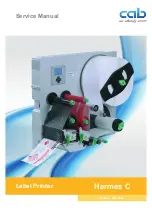
Page 1: ...User s Manual SLPA7000r Smart Label Printer Applicator SLPA8000 Smart Label Printer Applicator LPA8000 Label Printer Applicator...

Page 2: ......

Page 3: ...User s Manual SLPA7000r Smart Label Printer Applicator SLPA8000 Smart Label Printer Applicator LPA8000 Label Printer Applicator...

Page 4: ...nches for thermal transfer use whichever comes first The warranty does not cover printheads that have been misused damaged due to improper cleaning or damaged due to use of improper ribbons or media S...

Page 5: ...Darkness ___________________________ Machine Type ___________________________ Pinch Roller ___________________________ Random Stroke Delay ___________________________ Cycle Time Delay _______________...

Page 6: ...his device complies with part 15 of the FCC Rules Operation is subject to the following two conditions 1 this device may not cause harmful interference and 2 this device must accept any interference r...

Page 7: ...system meets the following technical standards EN 300 220 1 2000 Electromagnetic Compatibility and Radio Spectrum Matters Short Range Devices Radio equipment to be used in the 25 MHz to 1000 MHz freq...

Page 8: ...and PSA are registered trademarks of Printronix Inc IPDS is a trademark of International Business Machines Corporation LaserJet is a registered trademark of Hewlett Packard Company Microsoft MS DOS an...

Page 9: ...0 Overview 22 General Operation 22 Operating Specifications 23 Storage Shipping Handling 24 Safety 25 Warnings And Cautions 25 Operating Precautions 26 Operational Safety 26 Installing The SLPA 27 Unp...

Page 10: ...And Apply Process 69 3 Configuring The SLPA 71 Overview 71 Setting SLPA Configuration Parameters 71 Moving Within The Configuration Menu 71 Selecting A Menu Option 72 Changing SLPA Settings 72 Saving...

Page 11: ...WLAN LEAP 175 WLAN LEAP Submenus 175 BATTERY CONTROL 176 BATTERY CONTROL Submenus 177 DATE 179 DATE Submenus 179 Applicator Delay Menu 180 4 Interfaces 181 Overview 181 Auto Switching 181 IEEE 1284 P...

Page 12: ...Specifications 245 Applicator Orientation 245 Product Distance Variation 245 Application Rate 245 Printing 246 Media 247 Ribbon 248 Electrical 249 Pneumatic 249 Environmental 250 Physical 250 Connect...

Page 13: ...263 Loading Software If Flash Contains Only Boot Code 265 Loading Software Through The NIC 266 Downloading Optional Fonts To Flash Memory 268 Downloading TrueType Fonts 270 Printronix Windows Driver 2...

Page 14: ...14 Table of Contents...

Page 15: ...e problem with a new install or an existing SLPA Description of the problem be specific Good and bad samples that clearly show the problem faxing of these samples may be required Americas 714 368 2686...

Page 16: ...14 368 2300 Fax 714 368 2600 Printronix Inc Nederland BV P O Box 163 Nieuweweg 283 NL 6600 Ad Wijchen The Netherlands Phone 31 24 6489489 Fax 31 24 6489499 Printronix Schweiz GmbH 42 Changi South Stre...

Page 17: ...ioni che possono arrecare danni alle persone e alle apparecchiature CAUTION Conditions that could damage the SLPA or related equipment IMPORTANT Information vital to proper operation of the SLPA NOTE...

Page 18: ...1050 Proprinter IIIXL and Serial Matrix printers Printronix IGP PGL and IGP VGL Provides printer system commands for text barcodes graphics lines and boxes ZGL TGL IGL STGL and DGL Interpreters PPI ZG...

Page 19: ...AN Local Area Network rather than attaching it directly to a host computer NIC adapters are available as an internally installed option mounted inside the SLPA with the 10 100Base T UTP connection onl...

Page 20: ...nt premature wear of the printhead Thermal Printer Technology Unlike a dot matrix laser or LED printhead printer a thermal printer has a printhead containing heating elements that are used with paper...

Page 21: ...thermal dots If uneven print density occurs it is usually caused by the stored heat from dots printed previously The SLPA uses Dynamic Print Control technology to ensure even print density Dynamic Pr...

Page 22: ...al and thermal transfer label printer The SLPA can be positioned for top side or bottom applications and mounted using the mounting holes in either the base or sides NOTE Specify the orientation of th...

Page 23: ...phase 50 60 Hz or 230 VAC 10 single phase 50 60 Hz CAUTION It is recommended that you isolate the SLPA from its power supply by means of a surge suppressor to minimize any potential damage to the equi...

Page 24: ...r the printhead applicator label rollers and rear cover Carefully inspect the SLPA packaging upon receipt If damage from dropping crushing or punctures occurred contact the carrier directly and specif...

Page 25: ...ures requiring access to the rear compartment or power entry module of the SLPA WARNING Both surge protection for the electrical supply and pressure relief for the pneumatic supply are strongly recomm...

Page 26: ...med on the circuitry Do not use objects other than a finger to operate buttons on the keypad Sound pressure levels indicated a maximum reading of 81 1dB A Sound levels were determined based on SLPAs o...

Page 27: ...lly inspect each item for signs of damage Make certain that all parts options requested are received with the order 5 Consult the enclosed packing slip for contact information if any item is missing o...

Page 28: ...ck When mounting the SLPA use screws that will secure the assembly into place but will not penetrate deeper than 1 2 inch 12 7 mm in the SLPA IMPORTANT Retain cap screws in mounting holes that are not...

Page 29: ...he pad home port on the interface side panel Figure 3 2 Connect the interface cable to the serial data port 3 Connect the opposite end of the interface cable to the serial communications port of the h...

Page 30: ...available 7 Mount the air filter according to requirements NOTE Customer must provide the necessary mounting for the air filter supplied with the system 8 Connect the air supply hose to the air suppl...

Page 31: ...uring The SLPA on page 71 to customize printing setup 11 Adjust the air pressure to 90 10 psi using the air pressure adjustment knob and the air pressure gauge Figure 4 pull up the knob then rotate it...

Page 32: ...p of a flat tip screwdriver into the slot above the fuse holder assembly and twist to remove the assembly 3 Flip over the fuse holder assembly and make sure the fuse is in the active fuse location NOT...

Page 33: ...ds are given to the SLPA through the control panel keypad Control valves are provided for refined adjustments to the pneumatic system IMPORTANT It is important to become familiar with all of the opera...

Page 34: ...de Menu Mode Online Status indicator Indicates when SLPA is online offline or in fault condition Light is on when online ready to print and accept data from host Flashes during fault condition Light i...

Page 35: ...options Increases option values in submenus Menu key Data indicator Menu key Data indicator is green when data is in the system Takes the SLPA offline and selects Menu mode Enters Menu mode Scrolls t...

Page 36: ...t key prints a label and feeds it to the applicator pad if there is a label configuration in the SLPA s print buffer If no label pattern exists in the buffer it will not function In Menu mode the decr...

Page 37: ...set to Enable in the PRINTER CONTROL menu to use the Cancel key The default is Disable When the SLPA is offline the Cancel key clears the current print pattern and all printing programs currently in t...

Page 38: ...over the peel bar then to the applicator pad If the adjustment is too low the labels will not properly transfer from the printer to the applicator pad If set too high the label edge will be incorrect...

Page 39: ...Roll 39 Setup Threading The Label Roll Figure 8 The Printhead Assembly 1 Press the Pause key to take the SLPA offline 2 Open the pivoting deck by rotating the deck lock lever fully clockwise Pivoting...

Page 40: ...cam lock located on the collar of the label roll hub 4 Slide the label roll retainer off the label roll hub 5 Remove the empty label roll core if necessary from the label roll hub Label Roll Core Cam...

Page 41: ...lar so that it aligns with the flat edge of the label roll spindle 8 Place the label roll retainer onto the label roll spindle until it is flush with the label roll then tighten the black cam lock NOT...

Page 42: ...s a leader to thread the media through the SLPA components 10 Pull the brake assembly away from the label roll back stop behind the label roll retainer to release the tension 11 Thread the leader arou...

Page 43: ...de edge of the leader is against the fixed guide on the bottom of the media damper 15 Push the media width guide in until it is flush with the outer edge of the media NOTE Do not wrinkle the leader by...

Page 44: ...17 Slide the upper sensor directly over the lower sensor 18 Thread the leader between the printhead assembly and across the top of the platen roller Upper Media Sensor Visible Red Beam Lower Sensor Up...

Page 45: ...o the media rewind spool 22 Fold the leading edge of the leader and insert it into the slit on the rewind spool Make sure the leader lines up closely to the SLPA panel 23 Manually rotate the spool at...

Page 46: ...pivoting deck and printhead assembly into the printing position IMPORTANT Ensure the pivoting deck is down and locked before attempting to advance media or print Failure to do so will cause the PRINTH...

Page 47: ...erboard core comes with the SLPA Thereafter use the fiberboard core from the old used up ribbon 3 Slide the ribbon roll onto the ribbon supply spindle until it stops against the spindle flange 4 Open...

Page 48: ...on Through the Printhead Assembly 5 Thread the end of the ribbon under the rear ribbon guide roller then between the platen and the printhead using the dotted line etched on the front center wall plat...

Page 49: ...he ribbon take up core Manually rotate the spindle clockwise to feed the unusable portion of the ribbon leader around the take up spindle IMPORTANT Do not attach the ribbon to the ribbon take up spind...

Page 50: ...he air jet angle to a point beyond 1 3 the label length where shorter or narrower labels may target inside the 1 3 length zone Repeated adjustment may prove necessary for optimum operation Figure 19 P...

Page 51: ...blank labels by inserting the new edge of the label backing into the slit on the rewind spool and manually rotate the spool at least one turn counterclockwise 5 Press the Pause key to place the SLPA o...

Page 52: ...ct User Defined table select Main table enable GPIO Print Apply 1 Press the Menu key to take the SLPA offline and into Menu mode 2 Press and at the same time until ENTER SWITCH UNLOCKED displays 3 Pre...

Page 53: ...inthead Pressure Adjustment Adjust the printhead pressure to the setting of 4 The value shown at the bottom of the dial is the active pressure setting Left Pressure Block Left Pressure Block Handle Bo...

Page 54: ...cks Use the lead screw knob to position the right pressure block with its pointer near the right edge of the media in use Positioning The Media Sensors Figure 21 Adjusting the Media Sensors The SLPA i...

Page 55: ...dia sensor should not be placed in the path of media features that could cause false gap detection or paper out faults Such features are dark pre printing rounded die cut label corners and extraneous...

Page 56: ...of each label is based on the Label Length value entered in the QUICK SETUP menu or the value sent via host software Mark Select when using media that has horizontal black marks located on the undersi...

Page 57: ...w opening in the media guard Use the visible red light emitting from the lower sensor as a reference pointer 2 Use the sensor handle to manually position the sensor as close as possible to the center...

Page 58: ...under the center of the gap notch or hole 2 Check the position of the lower sensor by looking through the long narrow opening in the media guard Use the visible red light emitting from the lower senso...

Page 59: ...round on white or clear liner 1 Position the lower sensor so that the left edge of the beam is slightly to the right of the left edge of the die cut label directly under the center of the gap 2 Check...

Page 60: ...derside of the label interrupted by a notch or hole used as the label length indicator 1 Position the lower sensor so that the left edge of the beam is slightly to the right of the left edge of the di...

Page 61: ...ck mark When you have completed Auto or Manual Calibrate you can verify that the new values are correct by pressing the Feed key several times Each time you press Feed media advances one label and sto...

Page 62: ...lue displayed or a fault message displayed run Manual Calibrate as described on page 64 NOTE The amount of media sampled during Auto Calibrate is based on the length of a label and transitions detecte...

Page 63: ...edia Types on page 56 You will need a minimum installed label width of two inches to support the Profile printout Ensure the lower media sensor is horizontally positioned to permit sensing of the labe...

Page 64: ...The Gap Mark and Paper Out Threshold values shown on the Profile printout represent the last values determined from a successful Auto or Manual Calibrate or the factory default values if no Auto or M...

Page 65: ...er indicates that you must open the pivoting deck and remove the ribbon and media from under the printhead close and lock the pivoting deck and press the key During the last step of Manual Calibrate t...

Page 66: ...arning conditions Once the SLPA is online and configured if necessary for the desired application take the SLPA offline before downloading labels from the host into the buffer This will prevent any ch...

Page 67: ...the time that the applicator pad is online Since the label prints first be sure to account for printing time The longer the time entered the farther back closer to the trailing edge the label will be...

Page 68: ...am 3 Once the label is positioned in the desired location on the product secure the product sensor onto the conveyor If the SLPA cycles when a product is not in position a background object may be act...

Page 69: ...tact with the product 2 Use the flow control valve located on the air cylinder to adjust the speed of the return stroke Figure 28 Increase the speed by rotating the valve counterclockwise and decrease...

Page 70: ...70 Chapter 2 Printing And Applying Labels...

Page 71: ...not be present in your SLPA If you select an option or feature that is not present no action will be performed by the SLPA or an OPTION NOT INSTALLED message will display on the LCD Moving Within The...

Page 72: ...is function is performed while the key is unlocked the message ENTER SWITCH LOCKED displays for one second and the key will be locked When you press the key with the key unlocked you select the value...

Page 73: ...ys to access the value and the key to select it At any time you may press the Menu key to return to the Main menu 6 At any time you may press the Pause key twice to exit the Configuration menu and pla...

Page 74: ...lowing error message displays If the above occurs see Modifying A Saved Configuration on page 75 step 4 5 Print your configuration and store it in a safe place for future reference Refer to Printing A...

Page 75: ...ey to select it The following message displays NOTE If the configuration number has not been saved previously the following error message displays If this error message displays see Saving A Configura...

Page 76: ...ified configuration you must delete the original configuration if the Protect Configs option is enabled a Press the or key until the following message displays b Press the or key to cycle through the...

Page 77: ...4 When the desired option displays press the key The SLPA prints the specified configuration NOTE If the configuration you want to print has not been saved the following message displays momentarily...

Page 78: ...Print Speed Print Mode Media Handling Paper Feed Shift Label Length Label Width Ver Image Shift Hor Image Shift Orientation Auto Map Select Auto Label Width Num Auto Labels Slew Speed Print Direction...

Page 79: ...le 4 on page 112 If you change the Gap Mark Sensor or Paper Out Sensor you must recalibrate the media 2 Appears only if the CTHI option is installed 3 Appears only if RFID is installed 4 Appears only...

Page 80: ...ze Forms Handling PGL Normal UPC Descenders I 2 5 Selection User Def Ratio Lead PDF Dist Trunc Dyn Data Error Report Boundary Check Repeat Form Opt Preparser Cmd Preparser Port Ret Status Port NOTES I...

Page 81: ...H Installed DRAM Installed Ptr On Time Ptr Media Dist Head Print Dist Head On Time Reset Head Data Head Type Head Voltage PPI IGL SETUP 1 Refer to the Printer Protocol Interpreter PPI IGL Programmer s...

Page 82: ...y key is used C T PORT 1 page 160 Port Type Device Address Timeout Report Status ETHERNET ADDRESS 2 page 161 IP Address SEG1 IP Address SEG2 IP Address SEG3 IP Address SEG4 Subnet Mask SEG1 Subnet Mas...

Page 83: ...th WEP Key 2 BYTE1 WEP Key 2 BYTE2 WEP Key 2 BYTE3 WEP Key 2 BYTE4 WEP Key 2 BYTE5 WEP Key 2 BYTE6 3 WEP Key 2 BYTE7 3 WEP Key 2 BYTE8 3 WEP Key 2 BYTE9 3 WEP Key 2 BYTE10 3 WEP Key 2 BYTE11 3 WEP Key...

Page 84: ...alled 4 Appears only if the Real Time Clock option is installed GPIO CONTROL BATTERY CONTROL 1 page 176 Battery Monitor Time To Go 2 Percent Charge 2 Current Draw 2 Voltage 2 Amp Hour Used 2 Time To G...

Page 85: ...ips 1 to 10 ips1 Print Speed Print Mode Paper Feed Shift Label Width Label Length Orientation Transfer Direct 4 1 6 6 or 8 5 inches Portrait Landscape Inv Portrait Inv Landscape 3 15 to 15 00 1 to 4...

Page 86: ...ty and speed must match the media and ribbon type to obtain the best possible print quality and barcode grades The range is 15 through 15 The default is 3 Print Speed This menu item specifies the spee...

Page 87: ...etting up to a maximum of 12 80 inches in 0 01 inch increments Adjust the media so that the middle of the label gap is over the peel bar edge The default is 0 00 inches Label Length In most applicatio...

Page 88: ...rements The default value is 0 00 inches Orientation Specifies the image orientation to be used when printing the label Portrait the default Portrait refers to vertical page orientation where the heig...

Page 89: ...VGL emulations This is regarded as Portrait using PPI1 Inv Landscape Inverse Landscape refers to horizontal orientation where the width of a page is greater than its height The top edge of the image i...

Page 90: ...holes as label length indicators on white background media The top of form position is the leading edge of the die cut label trailing edge of the gap notch or hole Advanced Gap Select when using medi...

Page 91: ...hould match the length from the leading edge of one black mark to the leading edge of the next black mark Auto Calibrate supports label lengths up to 24 inches Active IGP Emul This function allows you...

Page 92: ...default The printer disables the use of the Software Migration Tools Enable The printer enables the use of the Software Migration Tools PAA Status See Software Migration Tools SMT in the RFID Labelin...

Page 93: ...ONTROL menu Load Config Factory 1 8 1 1 8 Current Factory Power Up All 1 8 Factory 1 8 Disable Enable 1 8 All 1 Save Config Print Config Delete Config Power Up Config Name Config 1 Protect Configs Nam...

Page 94: ...This option is used to print a listing of various stored printer configurations We recommend you store printouts of your configurations in a safe place for quick referral The options are Current the f...

Page 95: ...cter you have already modified Continue until you have entered the name you want to give to this configuration then press to save The name you entered will now represent this configuration on the prin...

Page 96: ...are available when Admin User is set to Enable in the PRINTER CONTROL menu 1 Maximvum value depends on the width of the printer model and printhead 2 You can change the unit value from inches to milli...

Page 97: ...ized items are available only when Admin User is set to Enable in the PRINTER CONTROL menu 6 The Peel Off option under Media Handling must be enabled for this menu to function 7 The Continuous option...

Page 98: ...Speed This option specifies the speed in inches per second ips at which the media passes through the printer while printing The range is 1 to 10 ips in increments of 1 ips The factory default is 6 ip...

Page 99: ...mum of 12 80 inches in 01 inch increments The factory default is 0 00 inches Label Length This option specifies the user selected Label Length in inches or millimeters In most applications the user se...

Page 100: ...CONTROL menu When the Logical Label Length is less than the Physical Label Length the printer will print the entire image and leave blank space the remaining length of the physical label as it advanc...

Page 101: ...e height of a page is greater than its width The top edge of the image is parallel to the leading edge of the media The following illustration is an example with the operator viewing the front of the...

Page 102: ...e used by the application The IGP Auto Label Mapping feature allows backward compatibility of programs written for P5000 line matrix printers using the Printronix PGL graphics language It allows the p...

Page 103: ...to Label Mapping feature Printer Operation The printer will print the first leftmost 4 label first Once the first label has been completed the printer will print the second 4 label These labels will a...

Page 104: ...tructed with three horizontally adjacent 4 labels The user now desires to use this file with a printer that has a 8 physical width The user should have used a solution similar to one of the solutions...

Page 105: ...inally once both of those labels have been printed the printer will print a blank 4 label Auto Label Width The width of a single label to be printed or the maximum width of the media that will be used...

Page 106: ...page 246 for slew speed specifications Print Direction This option determines the basic print image orientation NOTE Print Direction will not change the orientation of any print test patterns in the...

Page 107: ...e factory default is 1 0 second Lbl Missing Flt Allows the Label Taken Sensor to first detect the presence of a label at the tear bar for Peel and Tear Off Media Handling Mode only Enable the default...

Page 108: ...to Disable Mark and Gap media sensing reliability can be improved and the sensor problems described below can be fixed The image starts to print at an erroneous distance from the top of form especial...

Page 109: ...me As Paper Display Ribbon When enabled the remaining length of unused ribbon will display on the LCD when the printer is online The options are Enable the factory default and Disable Ribbon Low This...

Page 110: ...gth value in the CALIBRATE CTRL menu from the Sensed Distance value obtained when the Auto or Manual Calibrate was performed Peel Off Mode Prints and peels die cut labels from the liner without assist...

Page 111: ...nly Disable the default The printer assumes that the media is not at the correct TOF position after cycling power or after the printhead is opened and then closed and advances media until the next gap...

Page 112: ...In Millimeters option 3 When Gap Mark Sensor Disable Gap or Mark the default is 12 When Gap Mark Sensor Advanced Gap or Advanced Notch the default is 20 Table 4 Gap Mark and Paper Out Sensors When you...

Page 113: ...ced Notch Select when using media with notches or holes that interrupt a black vertical line on the underside of the media The Top of Form position is the leading edge of the die cut label trailing ed...

Page 114: ...exceeded by the output of the media sensor is recognized by the printer as a gap or black mark When Auto or Manual Paper Calibrate is performed the value displayed is equal to the gap mark threshold v...

Page 115: ...orrectly matches that of the installed media When Gap is selected the Sensed Distance should match the length from the trailing edge of one gap to the trailing edge of the next gap or one label one ga...

Page 116: ...enu option The result is that cross perforations or unusual media discrepancies within the gap are filtered out allowing the printer to reliably detect the actual leading edge of the next label and us...

Page 117: ...Calibrate Enable the default The Label Length value set in the QUICK SETUP or MEDIA CONTROL menu is used in the calibrate algorithm This causes the Auto Calibrate process to advance media the minimum...

Page 118: ...using a false TOF detection In most cases this can be resolved by selecting a higher threshold range so the printer will only trigger on the true TOF gap notch or mark position NOTE A new threshold ra...

Page 119: ...3 Notes Factory Default Italicized items are available only when Admin User is set to Enable in the PRINTER CONTROL menu 1 Appears only if the CT emulation is installed 2 Will not appear if a NIC is...

Page 120: ...the PRINTER CONTROL menu 8 Appears only if the PPI ZGL emulation is installed Ld Set from Flsh Save Set to Flsh Del Set from RAM Ld Set at PwrUp Disable Enable XXXXX XX 1 Del Char frm RAM Del Set frm...

Page 121: ...ilable only when Admin User is set to Enable in the PRINTER CONTROL menu OCR A Chars 0 512 384 OCR B Chars 0 512 304 Tall Characters Enable Disable PRINTER CONTROL cont from previous page Admin User D...

Page 122: ...e line or dot matrix printer to be emulated by the printer P Series the default P Series XQ Serial Matrix Proprinter XL Epson FX CTHI Emulation This item appears only when the CTHI option is installed...

Page 123: ...s available in your thermal printer Centronics serial coax and twinax Also supported are Epson Proprinter XL P Series Serial Matrix VGL and PGL emulations The SPC has the ability to handle multiple pr...

Page 124: ...h Label Width and other settings in use will change to the settings saved under the Power Up Config menu Therefore insure that all desired settings are saved as the printer Power Up Config menu settin...

Page 125: ...nline state Offline The printer powers up in the offline state This selection must be saved as a power up configuration to be used PTX Setup SFCC Allows you to choose the hex value of the ASCII charac...

Page 126: ...hermal printers T1006 Forces the output to correspond with the T1006 line of thermal printers The factory default is Default Set Sharing This option allows character sets to be shared between the acti...

Page 127: ...Enable Overwrite Files This allows you to prevent files from being overwritten by disabling the overwrite function The options are Enable the default and Disable View File List Displays the list of f...

Page 128: ...combination of keys that you want to be the new lock key Make sure you press all keys selected at the same time 4 If the selection is valid the display will read Enter the new lock key again Press the...

Page 129: ...100 to 800 Kbytes and the factory default is 100 Kbytes Max Cache Memory The Maximum Cache Memory option specifies the size of the memory block that can be allocated to the font cache The font cache...

Page 130: ...tandard Chars This menu entry permits you to adjust the thickness or font weight of standard text fonts The range is 0 to 512 and the factory default is 340 Bold Chars This menu entry permits you to a...

Page 131: ...the number of pages remaining in a print job Disable the default The Pages remaining to be printed will not display Instead the Active emulation and interface will display on the second line of the co...

Page 132: ...ode Autowrap Auto Uppercase Slash 0 Select SFCC Host Form Length Var Form Adjust Optimized Ratio Greek Sets Hebrew Sets Turkish Sets 3 Danish 4 Norwegian 2 Swedish 0 ASCII 1 German 5 Finnish 6 English...

Page 133: ...ces Select SO Char Ignore Mode Select Char Do FF at TOF IGP100 Compatbl Expanded Font Scalable Size Forms Handling Ignore Text Disable Enable Enable Disable Disable Enable Disable Enable 14 0 to 255 D...

Page 134: ...r Report Repeat Form Opt Only With PDF Never Always Fault Debug Mode On Off Enable Disable X2 DPD Trailing Space Leading Zero Modulo 7 CD Enable Disable Lead PDF Dist 0 01 to 0 10 inches 0 10 inches P...

Page 135: ...n 2 8859 2 Code Page 852 Mazovia Kamenicky Roman 8 PC 437 Slavic Slavic 1250 Code Page 865 Code Page 860 Latin 1 8859 1 Latin 5 8859 9 Latin 9 8859 15 Polish POL1 Win CP 1250 Win CP 1252 Win CP 1257 C...

Page 136: ...tra line feed after each carriage return The next print position will be print position 1 of the next line Define LF Code This parameter forces the printer to insert an automatic Carriage Return code...

Page 137: ...gth Determines how the physical label length see Label Length under the MEDIA CONTROL menu is affected upon receiving an EXECUTE command Enable the default The physical label length will change to mat...

Page 138: ...Ratio This option selects different bar code ratios for certain bar codes including Code 39 and Interleaved 2 of 5 It is included for compatibility with the IGP X00 printers Disable the default Use st...

Page 139: ...data etc are allowed within a form where the Form Count parameter is specified in the Execute command In this case the same form is printed for whatever the Form Count is Incremental data is not incre...

Page 140: ...ausing a blank form Disable The printer will not advance media from the present TOF position to the next TOF position upon receipt of an FF command IGP100 Compatibl This parameter forces the output to...

Page 141: ...EAN bar codes are printed with descenders even if there is no human readable data Never UPC EAN bar codes are printed without descenders if the PDF command is present Only With PDF UPC EAN bar codes a...

Page 142: ...or will report Enable If the dynamic data exceeds the maximum data length the data truncates Error Report This item sets the error reporting capability of the printer for PGL forms as follows On the d...

Page 143: ...unrelated to one another Preparser Cmd Allows users to select which preparser command to use Once the command is selected the command will be executed immediately when it is sent to the printer Statu...

Page 144: ...t Test Right Test Barcode Demo Head Voltage XXXXX Inches 3 XXXXX Inches 3 XXX X Hours 3 XX X Hours 3 XXX DPI 3 XX XX X XX volts 3 1 Page 2 Pages 5 Pages 10 Pages Disable Enable Factory Default 1 Appea...

Page 145: ...containing a series of ladder type bar code symbols starting with four and decrementing by one symbol on each print until a single symbol prints on the right side This pattern helps identify ribbon w...

Page 146: ...Installed Displays the amount of FLASH memory installed in megabytes DRAM Installed Displays the amount of DRAM installed in megabytes Ptr On Time Displays the cumulative time in hours the printer has...

Page 147: ...set Head Data Resets all printhead statistics values Head Prt Dist and Head On Time to zero Head Type Displays the printhead type installed in dots per inch 203 dpi or 300 dpi Head Voltage Displays th...

Page 148: ...when Admin User is enabled in the PRINTER CONTROL menu 1 Does not display when Ethernet is installed 2 Available only when Ethernet is installed 3 Available only when the Centronics option is enabled...

Page 149: ...bit 8 is interpreted as either data bit 8 or PI signal but never both When enabled as data bit 8 data bit 8 has priority over the PI signal and all data above hex 7F is used to access character data a...

Page 150: ...selected value is the time that the printer waits before getting the next byte of data from the host The Trickle Time value should be less than the host time out value but not too much shorter or else...

Page 151: ...er must be set to match the response polarity of your host computer Standard the default Does not invert the response signal Inverted Inverts the response signal sent to the host computer Busy on Stro...

Page 152: ...sec 8 sec 16 sec Off 115200 BAUD Stop Bits Parity Mark Even Odd None Sense Buffer Size in K 16 1 16 Timeout 10 sec 1 60 sec Report Status Disable Enable Data Term Ready On Line and BNF True Off Line...

Page 153: ...erience data loss you may need to lower the baud rate or use RS 422 You also may need to increase the Buffer Size in K parameter from the default 1 Kbyte to improve performance The factory default is...

Page 154: ...ter controls the flow of communication from the host by turning the transmission on and off using response characters sent to the host If the number of valid bytes in the buffer reaches 75 percent of...

Page 155: ...re data If the host sends data during an unsafe condition data will be lost DTR is not available when RS 422 is selected Buffer Size in K This option configures the amount of memory allocated for the...

Page 156: ...1 4 sec Timeout This is the value used by the printer to time out from the current port and check the other selected Port Types for data to print When the printer has not received data from the host...

Page 157: ...rue Continuously asserts the RTS signal Poll Character This option is for the Series1 protocol Whenever the printer receives this character it sends a response to the host indicating the current state...

Page 158: ...ill respond to an ENQ character by sending a status byte to the host The type of status byte is determined by a Front Panel Menu selection The selections allowed are ENQ STX and ENQ The ENQ is removed...

Page 159: ...error occurs a fault message will display on the control panel Disable If a framing error occurs a fault message will not display on the control panel Table 7 ENQ Status Byte Bit Printer Status 0 Set...

Page 160: ...out This item allows you to set the time that the printer when it has not received data from its host will begin to service all other host ports looking for data to print The range is 5 to 60 seconds...

Page 161: ...s SEG2 000 0 to 255 IP Address SEG3 000 0 to 255 IP Address SEG4 000 0 to 255 Subnet Mask SEG1 000 0 to 255 Subnet Mask SEG2 000 0 to 255 Subnet Mask SEG3 000 0 to 255 Subnet Mask SEG4 000 0 to 255 Ga...

Page 162: ...the printer is placed online When the printer resets the NIC the LCD displays DO NOT POWER OFF After the NIC has completed its initialization the LCD displays E NET INIT to signal that the NIC and pr...

Page 163: ...nap Notes Factory Default 1 Appears only if a NIC is installed 2 Set the port number that works with your host system 3 Appears only if the IPDS emulation is installed ETHERNET PARAMS 1 ASCII Data Por...

Page 164: ...n of the frame type for the Novell protocol For the definition of each frame type refer to the appropriate Novell authorized documents The factory default is Auto Sensing ASCII Data Port This option a...

Page 165: ...d using half duplex 10 Full Duplex Tells the 10 100Base T NIC to communicate at 10 Megabits per second using full duplex 100 Half Duplex Tells the 10 100Base T NIC to communicate at 100 Megabits per s...

Page 166: ...SEG1 000 WLAN ADDRESS 1 0 255 IP Address SEG2 000 0 255 IP Address SEG3 000 0 255 IP Address SEG4 000 0 255 Subnet Mask SEG1 000 0 255 Subnet Mask SEG2 000 0 255 Subnet Mask SEG3 000 0 255 Subnet Mas...

Page 167: ...d online When the printer resets the NIC the LCD displays DO NOT POWER OFF After the NIC has completed its initialization the LCD displays E NET INIT to signal that the NIC and printer are in the init...

Page 168: ...01 15 101 SSID Name 16 30 SSID Name 31 32 Reset SSID Name Ad Hoc Min Xfer Rate Auto negotiate 1Mb sec 2Mb sec 5 5Mb sec 11Mb sec Ant Diversity Diverse Primary Auxiliary Signal Strength XX 2 Internat M...

Page 169: ...1 BYTE5 WEP Key 1 3 BYTE6 WEP Key 1 3 BYTE7 WEP Key 1 3 BYTE8 Continued at the top of next page WEP Key 1 3 BYTE9 WLAN PARAMS cont from prev page WEP Key 1 BYTE1 WEP Key 1 3 BYTE10 WEP Key 1 3 BYTE11...

Page 170: ...Key 2 4 BYTE8 WEP Key 2 4 BYTE9 WEP Key 2 4 BYTE10 WEP Key 2 4 BYTE11 WEP Key 2 4 BYTE12 WEP Key 2 4 BYTE13 WEP Key 3 Format Hexadecimal ASCII WEP Key 3 Width 128 Bits 40 Bits WEP Key 3 BYTE2 WEP Key...

Page 171: ...P Key 3 5 BYTE10 WEP Key 3 5 BYTE11 WEP Key 3 5 BYTE12 WEP Key 3 5 BYTE13 Notes Factory Default 5 Appears only if WEP Key 3 Width is set to 128 Bits Continued at the top of next page WEP Key 4 Format...

Page 172: ...ugh an Access Point Pseudo IBSS Proprietary peer to peer communication without an Access Point The two peers must be specific to one manufacturer Ad Hoc Standard peer to peer communication without an...

Page 173: ...the factory default and 1 15 Ant Diversity The type of antenna used Diverse the default Select when you want to use the antenna with the best reception Primary Select when you want to use the Primary...

Page 174: ...its The more bits you choose the more difficult it will be to decode the information NOTE None of the WEP Key Configuration menus display on the configuration printout WEP Key Format Allows you to for...

Page 175: ...acters 31 to 32 of the LEAP user name maximum number of characters is 32 Reset LEAP User Resets the LEAP user name to an empty string LEAP Password LEAP Password 01 15 The first 15 characters of the L...

Page 176: ...select Enable in the Battery Monitor submenu in the BATTERY CONTROL menu 2 You cannot change this value it is a display only item BATTERY CONTROL Voltage 1 Time To Go Alert 1 High Volt Alert 1 Amp Ho...

Page 177: ...menu is available only when you select Enable in the Battery Monitor submenu When the power cart charger is connected to an AC outlet the Time To Go will be 0 00 Hours This message updates approximat...

Page 178: ...ry default is 16 0 Volts NOTE This menu is available only when you select Enable in the Battery Monitor submenu Low Volt Alert This allows you to set the minimum voltage for determining when a BATT LO...

Page 179: ...s from 2000 to 2099 and the factory default is 2099 Month The month ranges from January to December and the factory default is January Day The day ranges from 01 to 31 and the factory default is 01 Mi...

Page 180: ...he SLPA back online SAVING DELAY TIMES will display briefly Cycle Delay Sets the length of time the product sensor detects the product until it applies the label Cylinder Extend Sets the length of ela...

Page 181: ...e ability to handle multiple data streams sequentially With Auto Switching the printer can service hosts attached to the serial parallel USB coax and twinax ports as if they were the only interface co...

Page 182: ...one nibble Two sequential four bit nibbles are sent over the lines Data is transferred from printer to host in four bit nibbles over the status lines and the host controls the transmission Byte Mode...

Page 183: ...nal Ground Data 1 21 Signal Ground Data 2 22 Signal Ground Data 3 23 Signal Ground Data 4 24 Signal Ground Data 5 25 Signal Ground Data 6 26 Signal Ground Data 7 27 Signal Ground Data 8 28 Signal Grou...

Page 184: ...a bits 2 and 6 in Nibble Mode Host Busy Host Acknowledge NDStrobe Driven by the host Activates auto line feed mode Peripheral Logic High Driven by the printer When the line is high the printer indicat...

Page 185: ...stream to the printer Transmitted Data TXD Serial data stream from the printer for transmitting status and control information to the host Subject to protocol selection Request To Send RTS Control sig...

Page 186: ...annot be used to transfer binary data to the printer such as the data contained in a Program Download To do a Program Download through the USB Port perform the following steps 1 Make the printer shara...

Page 187: ...n media debris may accumulate around the printer mechanism Clean the printhead area with the Printronix cleaning kit Use a soft bristle brush or vacuum cleaner to dust the interior CAUTION Never use m...

Page 188: ...eaning Figure 29 Cleaning the Printhead Pivoting Deck Deck Lock Lever Printhead Heating Elements Lower Media Sensor with visible red LED Printhead Cover Upper Media Sensor Platen Roller A A Upper Sens...

Page 189: ...IMPORTANT Do not use sharp objects such as a knife or screwdriver to remove stuck labels Media Sensor Cleaning The Upper and Lower Media Sensors should be cleaned to ensure reliable TOF and paper out...

Page 190: ...g agent should be used to clean the applicator pad Perform a maintenance check of the applicator pad vacuum chamber approximately every three months at minimum using the following procedures 1 Remove...

Page 191: ...cted for leaks then the vacuum generator should be cleaned as follows 1 Locate the vacuum generator inside the electrical enclosure on the applicator side of the SLPA see Figure 31 The vacuum generato...

Page 192: ...e for general day to day cleaning of the SLPA parts To keep the machine running smoothly adhere to the following guidelines Table 10 General Cleaning Schedule Items To Be Serviced Frequency How To Cle...

Page 193: ...that it takes a great deal of heat to make a clear image Resin ribbons and film media may also require higher print intensity for a quality image You can increase the heat applied by the printhead in...

Page 194: ...e slightly until you have good print quality 3 Avoid excessively high Intensity settings Intensity is the burn temperature that the printhead operates at Lower temperatures will increase the life of p...

Page 195: ...aining system at a time until the final half is a field replaceable part or assembly WARNING ALWAYS disconnect the AC power cord from the printer or the power outlet before doing any maintenance proce...

Page 196: ...Handling is set to Tear Off Strip or Continuous in the QUICK SETUP menu 1 Press the Pause key to take the SLPA offline 2 Press the Apply key to enter the Printer Tests menu 3 Press the Apply key until...

Page 197: ...rface card Barcode Demo Prints text and barcodes with the barcodes positioned at the left and right margins of the standard label media supplied with the SLPA NOTE To print a complete version of self...

Page 198: ...layed Message Can User Correct Explanation Solution 06 HOST REQUEST Yes Status message in CT emulation the host computer or printer controller requires attention Not a printer problem 08 HOLD PRINT TI...

Page 199: ...ffline more than 10 minutes and the Intervention Required parameter is set to Send to Host Close and latch the printhead Press PAUSE to put the printer online 40V POWER FAIL Yes 40 VDC an internal pow...

Page 200: ...er data format Fix application so it sends data in the correct bar code format BAR CODE QUIET Zone too small Yes Data validation error Quiet Zone error 1 Fix application 2 Disable Quiet Zone Error rep...

Page 201: ...rial interface 1 Make a configuration printout 2 Verify that the printer matches the host serial interface configuration settings for Data Protocol Baud Rate Data Bits Stop Bits Parity Data Terminal R...

Page 202: ...catch labels during Auto Calibrate 1 Select another Media Handling option in the QUICK SETUP or MEDIA CONTROL menu 2 Enable Cal in Peel Mode in the CALIBRATE CTRL menu NOTE Admin User must Enable Chec...

Page 203: ...when you set Battery Monitor Enable in the BATTERY CONTROL menu No action required DIAGNOSTICS PASSED Yes The printer passed its memory and hardware initialization tests No action required DIRECT THER...

Page 204: ...the display message and send it to your next higher support facility E01A TYPE 0x40 See User Manual Yes An illegal or unsupported instruction was attempted in the application program 1 Cycle Power Run...

Page 205: ...y message and send it to your next higher support facility E03B DSI HASH S See User Manual Yes An illegal or unsupported instruction was attempted in the application program 1 Cycle Power Run the prin...

Page 206: ...rd the display message and send it to your next higher support facility E03F DSI CXOWX See User Manual Yes An illegal or unsupported instruction was attempted in the application program 1 Cycle Power...

Page 207: ...y message and send it to your next higher support facility E04B ISI DIRECT See User Manual Yes An illegal or unsupported instruction was attempted in the application program 1 Cycle Power Run the prin...

Page 208: ...send it to your next higher support facility E08 FLOATINGPNT See User Manual Yes An illegal or unsupported instruction was attempted in the application program 1 Cycle Power Run the print job again I...

Page 209: ...n If the problem persists contact your authorized customer service representative ERROR IPDS needs 300 DPI Head Yes The printer has detected a 203 DPI printhead installed with IPDS software downloaded...

Page 210: ...inter for 15 seconds then power back on If the problem persists contact your authorized customer service representative ERROR WRITING TO FLASH Yes No Hardware or software fault in flash memory Power o...

Page 211: ...FILE SYS FULL Add Flash Yes No Insufficient flash memory available to store file Install a larger flash memory SIMM For additional flash contact your authorized service representative FILE SYS FULL D...

Page 212: ...r media sensor Gap Mark Threshold is set too high or Paper Out Threshold is set too low 1 Check that the setting of the Gap Mark Sensor in the CALIBRATE CTRL menu matches the installed media 2 Check t...

Page 213: ...ed Mode Yes The printhead or power supply is approaching a hot state Half Speed Mode helps the cooling process and should permit completion of print jobs Half Speed Mode helps prevent a PRINT HEAD HOT...

Page 214: ...the tear bar with Tear Off or Peel Off Media Handling mode enabled The label was removed before the printer stopped printing or before the LCD Remove Label message displayed The label slipped behind t...

Page 215: ...n Menu mode when no validator option is installed No action required INCOMPATIBLE WITH CUTTER Yes Tear Off or Peel Off Media Handling selection was attempted with the cutter option still installed The...

Page 216: ...he printer is out of memory and will not save that or subsequent configurations Previously saved configurations are still okay 3 Limit the number of saved configurations to seven OPTION NOT INSTALLED...

Page 217: ...lation procedures on page 39 2 Verify the lower media sensor is properly positioned under the media If Advanced Gap or Advanced Notch is selected verify the upper media sensor is positioned above the...

Page 218: ...bar code elements is too small Adjust heat speed pressure POOR SCANNING Check media Yes Data validation failure The bar code is only good in small bands that are difficult to scan Check for ribbon wri...

Page 219: ...AD UP Close Print Head Yes Printhead is not closed and completely latched Close and latch the printhead pivoting deck PRINTER HOT See Manual Yes No The printer has detected higher than usual temperatu...

Page 220: ...NG HOST SERIAL Yes Normal message that displays when you set Validator Funct Disable in the VALIDATOR menu or Battery Monitor Disable in the BATTERY CONTROL menu No action required RECHARGE BATTERY Ye...

Page 221: ...to flash memory and is automatically resetting itself No action required RESTORING BOOT CODE Yes Normal download initialization message No action required RFID TAG FAILED Check Media Yes Failed tag Er...

Page 222: ...pool then the Ribbon Low message is being displayed falsely 1 Replace ribbon 2 Disable Ribbon Low in the MEDIA CONTROL menu RIBBON OUT Load Ribbon Yes 1 The ribbon supply spool is empty 2 The ribbon h...

Page 223: ...ssage Printer is running its initialization routine 1 No action required 2 If the printer does not complete initialization and continues displaying this message when the CT emulation is installed the...

Page 224: ...ter power WIRELESS ADAPTER NOT COMPATIBLE No The type of wireless card is incompatible with the printer software The PCMCIA radio card that you installed may be incompatible with the dual NIC interfac...

Page 225: ...outlet before doing a maintenance procedure Failure to remove power could result in injury to you or damage to equipment If you must apply power during maintenance you will be instructed to do so in...

Page 226: ...ated and the printer appears to be working but nothing is printed 1 Verify that the labels are the correct type direct thermal 2 Check that the media is loaded with the direct thermal side facing up 3...

Page 227: ...bly ONLINE status indicator is flashing 1 Check for Out of Media condition or missing labels in the middle of a roll Load correct media 2 Check that the ribbon and label stock are correctly routed Loa...

Page 228: ...and 40VDC are good test at TP3 VCC for 5VDC 4 75 to 5 25VDC If voltage is not in tolerance replace the controller PCBA 8 If all voltages are good so far test for 3 3VDC 3 14 to 3 47VDC on the center l...

Page 229: ...test pattern page 196 If the pattern prints there is a communication problem between the host computer and the printer 2 Make sure the J402 power supply cable has a good connection to the right side...

Page 230: ...DIA CONTROL menu 7 The head pressure adjustment dial may be set too low Readjust 8 The Print Intensity value is set too low in the QUICK SETUP or MEDIA CONTROL menu or by host software 9 The printhead...

Page 231: ...allel interface is being used make sure the parallel interface terminating resistors are correct for the host computer drivers Peel Off or Tear Off Media Handling is selected but the printer does not...

Page 232: ...used by severely curled labels near the end of a media roll the media sensor triggering off of a dark preprinted image on the label multiple gaps within the physical label Loss of one or more serializ...

Page 233: ...l and a cotton swab 7 Print the checkerboard and grey diagnostic test patterns page 196 8 Verify that the head pressure blocks are positioned to match the width of the media being used See Printhead P...

Page 234: ...printhead may have nicks scratches grooves or cracks If no problem is visible install the printhead and repeat step 7 16 Install an alternate printhead if one is available and repeat step 7 17 If pos...

Page 235: ...correctly See Threading The Label Roll on page 39 2 Check that the Label Length selected under the QUICK SETUP or MEDIA CONTROL menu or the Label Length software command sent by the host computer agre...

Page 236: ...f and the beginning of the next label was printed on that same label 1 If the serial interface is being used verify that the selected data protocol for the printer matches that of the host computer 2...

Page 237: ...ump mode if it is a non IPDS printer to find what the SFCC character is 4 If the printer also has IPDS microcode installed ensure the customer is not using an IPDS device profile to send the IGP or Co...

Page 238: ...eat setting Print Intensity is set to the proper level In the QUICK SETUP or MEDIA CONTROL menu set Print Intensity to the correct level 2 Verify that Print Speed is not too low In the QUICK SETUP or...

Page 239: ...orque on the ribbon take up spindle The printer loses data from the print job when an end of ribbon condition occurs while printing even when Error Recover is set to Enable Use a Printronix ribbon NOT...

Page 240: ...80 psi The cylinder pressure should be approximately 40 to 60 psi on the control panel 4 Repair chinked air lines or broken and leaking fittings 5 Check air input and output from the valve Also check...

Page 241: ...Applicator Delay menu between 40 60 Labels not peeling off onto the tamp pad assembly 1 Check label tension around the peel plate 2 Verify that the labels are not expired or defective 3 Verify that t...

Page 242: ...V to valve If still no air jet stream check the connector Check the air solenoid valve is connected to the vacuum generator 2 Adjust vacuum valve clockwise for 20 in hg Check for obstruction in the va...

Page 243: ...Verify that the dancer spring is attached Replace the dancer spring if worn 3 The LED should be on when the dancer roller is in the up position If not check the connections and the 24vdc power supply...

Page 244: ...244 Chapter 6 Troubleshooting Other Symptoms...

Page 245: ...nique mode to determine maximum cycle rate for a particular application and label size The following factors below can significantly effect or reduce the total product speed within a target environmen...

Page 246: ...There has to be some minimum times between apply signals The number of cases that pass the applicator in a minute does not determine the case rate of a system Instead the rate is determined as a func...

Page 247: ...nting Width 3 0 to 4 1 inches 75 to 104 mm Printing Length 2 0 to 10 inches 50 8 to 254 mm Gap for 100 Printing 0 10 inches 2 54 mm Thickness 0 0025 to 0 0100 inches 0 0635 to 0 254 mm I Tag Specifica...

Page 248: ...0 10 in 2 54 mm I Min Refl Mark Width 0 5 in 12 7 mm E Media Thickness Range 0025 010 in 0635 254 mm G Width of Inter label gap hole 0 25 0 50 in 6 35 12 7 mm D Media Length Range 2 in 8 in These figu...

Page 249: ...andard IEC appliance coupler on one end and a main plug on the other end which is suitable for use and application of the product and is approved for use in the country of application Pneumatic Input...

Page 250: ...conditions with its environmental enclosure Operating Humidity Storage Humidity 20 to 85 non condensing 5 to 85 non condensing Liquids Free of direct fluid contact Solids Minimize unnecessary exposur...

Page 251: ...nections The serial ports must be configured for the correct baud rate parity and stop bits Communications Interface Standard interfaces include RS 232 only if RFID is disabled and IEEE 1284 Centronic...

Page 252: ...252 Appendix A Communications Interface...

Page 253: ...ed Warning An illuminated amber beacon signals a low label situation This signal state allows operation to continue but the operator is prompted to check the system s status Label On Pad Sensor The se...

Page 254: ...t before mounting the SLPA to the conveyor line To mount the beacon post 1 Orient the mounting holes of the beacon to the holes on the side panel of the SLPA and secure into place using the provided s...

Page 255: ...es the U arm configuration 1 Secure the support rod to the side plates of the SLPA using the two washers and four socket screws provided If the U arm was purchased with your SLPA this may already be d...

Page 256: ...arm clamps The weight distribution of the SLPA is not balanced therefore it would tend to pivot on the support rods The U arm clamps will supply enough pressure to hold the SLPA into place Mounting S...

Page 257: ...ing as it is located behind the media unwind assembly Its position may be moved to allow more or less media stock on the unwind roll before signal activation Proceed as follows 1 Remove the front labe...

Page 258: ...the signal state does not change the sensor and it s wiring may need maintenance Product Sensor Figure 37 Product Sensor Adjustment The product sensor mounts on the side of the conveyor and detects th...

Page 259: ...detected by the sensor NOTE For a standard SLPA the sensor should be set to Light Operate mode If the Dark Operator mode is required custom work is needed and must therefore be specified prior to ord...

Page 260: ...more than 11 50 inches 292 mm from the product to make contact Soft Pad For applications requiring cushioned application a soft applicator pad is available This pad is manufactured from foam rubber r...

Page 261: ...l copy the appropriate file from the CD ROM to a computer s hard disk then download the file from the computer into SLPA memory IMPORTANT When downloading emulation and operating system software to th...

Page 262: ...m see your system administrator Conditions for use of the included Java Software are set forth in the Sun Microsystems Binary Code License Agreement http java com en download license jsp In the event...

Page 263: ...d the SLPA may not boot up 15 When the new software has successfully loaded into flash memory and the SLPA has reset itself set the SLPA power switch to O Off 16 Remove the CD ROM from your computer a...

Page 264: ...er plus exe For example 123456 exe This is the file you will download into the SLPA 12 Copy the file to the download directory you created in step 8 13 Start a command prompt session The Start Menu ic...

Page 265: ...port is available In some configurations you may have to re install the Centronics I O cable and connector in order to load basic software into the SLPA 2 Set the SLPA power switch to O Off 3 Disconne...

Page 266: ...g DOS procedure In other words use the two key method to load software again This ensures that all necessary code is loaded into SLPA memory Loading Software Through The NIC IMPORTANT To load software...

Page 267: ...g in to the SLPA by typing root Enter You are given a password prompt NOTE The default is no password If the FTP program requires a password contact the system administrator 15 At the password prompt...

Page 268: ...onding part numbers Table 15 Optional Fonts Font Name Part Number Antique Olive 706612 001 Avante Garde 706617 001 Baskerville 706606 001 Caslon 706613 001 CG Bodoni 706610 001 CG Century 706598 001 C...

Page 269: ...ons and interfaces installed in the SLPA 8 Insert the optional font diskette into diskette drive A or B of the computer 9 Start a command prompt session The Start Menu icon is usually labeled MS DOS P...

Page 270: ...reset itself and go online 15 To verify that the optional fonts have been downloaded NOTE Admin User must be set to Enable in the PRINTER CONTROL menu See PRINTER CONTROL Submenus on page 122 a Perfor...

Page 271: ...d 5 Click the Download button to download font s to the SLPA while it is online Create And Send Download File Online PGL Only A TrueType font can be loaded by creating a file that appends a PGL comman...

Page 272: ...ut the SLPA in download mode as described in the Downloading Optional Font Files To Flash Memory section 6 Send the downloadable font file e g arial dwn to the SLPA through the appropriate I O port of...

Page 273: ...oading the TrueType font using any of the above methods the user can access the downloaded TrueType fot by using the FONT NAME command as described in the PGL Programmer s Reference Manual For Example...

Page 274: ...274 Appendix C Loading Flash Memory...

Page 275: ...otch media sensing 56 60 AI 00 Spaces option 139 Air connection 29 Air cylinder regulator control valve 38 Air jet adjustment control valve 38 AIR JET control valve 38 Air jets position 50 Air supply...

Page 276: ...3 Calibrating media sensors 61 CALIBRATION Warning fault message 202 Calibration warning fault message 202 Cancel Key option 125 CANNOT CALIBRATE Disable Peel Off fault message 202 Cautions 25 Changin...

Page 277: ...GL Serial Matrix Proprinter XL Epson FX 136 Del Char frm Flsh option 126 Del Char frm RAM option 126 Del Set frm Flsh option 127 Del Set from RAM option 127 Delete Config option 94 Delete Files option...

Page 278: ...Report option 142 ERROR SECURITY KEY NOT DETECTED fault message 210 ERROR SHORT AT ADDRESS XXXX fault message 210 ERROR WRITING TO FLASH fault message 210 ERROR WRONG CHECKSUM fault message 210 ETHER...

Page 279: ...r Path 214 LOADING PROGRAM FROM PORT XX 215 LOADING PROGRAM INTO FLASH 215 MENU MODE QUICK SETUP 215 NON VOLATILE MEMORY FAILED 216 OPTION NOT INSTALLED 216 PAPER OUT Load Paper 217 PAPER OUT TIMEOUT...

Page 280: ...M loading 261 Fonts 18 19 Downloading 268 Downloading TrueType 270 Forms Handling option 141 FPGA FILE NOT FOUND fault message 212 FRAMING ERROR fault message 212 Framing Errors option 159 Functions k...

Page 281: ...L MISSING Check Paper Path fault message 214 Label on Pad Sensor 253 Label print process 69 Label roll threading 39 Label sensor low 257 Label Width option 87 100 Labeling Applications 272 Latch Data...

Page 282: ...ring 198 Min Calib Delta option 117 Min Xfer Rate option 173 Minute option 179 Mode Applicator delay menu 180 menu 37 offline 36 online 36 Printer Tests 196 Modifying saved configurations 75 Month opt...

Page 283: ...and gauges 38 Pneumatic specifications 249 Poll Character option 157 Poll Response option 157 POOR SCANNING Check Head Heat fault message 218 POOR SCANNING Inspect head fault message 218 POR option 1...

Page 284: ...OT fault message 220 Pwr Up Auto Cal option 115 Q QUICK SETUP menu 85 submenus 86 R Random Stroke Sensor 260 Rate application specifications 245 Rbn Takeup Full option 109 RBN TAKEUP FULL Remove Used...

Page 285: ...140 Schedule cleaning 192 SECURITY CODE VIOLATION fault message 222 Select Char option 140 Select LPI option 136 Select SFCC option PGL 137 Select SO Char option 139 Selecting a menu option 72 Sensed...

Page 286: ...o option 177 Timeout option C T port 160 parallel port 150 serial port 156 TOF Adjust Mode option 111 TOF Adjust option 111 TOF Detect Fault option 110 Transmit Power option 174 Transmitted Data TD si...

Page 287: ...n 174 WEP Key Width option 174 Windows Driver 271 WIRELESS ADAPTER NOT COMPATIBLE fault message 224 WLAN ADDRESS menu 166 submenus 167 WLAN LEAP menu 175 WLAN LEAP menu Auth Method 175 LEAP Password 1...

Page 288: ...288...

Page 289: ......

Page 290: ...250117 001B 250117 001...

Reviews: