5–22
Alignments and Adjustments
Magnetic Pickup Phasing Adjustment
(Figure 5–9)
NOTE: Unless otherwise directed, perform the MPU gap adjustment (page
5–20) before proceeding.
NOTE: The quality of the phasing adjustment will be affected by the
condition of the shuttle bearings. If they have been tampered with or
damaged, the shuttle assembly should be returned for repair.
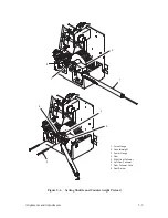
1. Loosen the screw (1) until the MPU arm (2) can be pivoted, but only
with some effort.
2. Load the printer with 14 7/8 inch wide, single–part paper.
3. Refer to the P9012 User’s Manual and command a 132 column self–test,
printing all “H’s.” Observe the printout. The relative horizontal position
of dots in alternate rows should be as shown below. If either incorrect
condition is observed, position the MPU arm until the dots in succeeding
rows are aligned horizontally to within 0.005 inch.
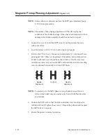
Needs
Alignment
Correct
Needs
Alignment
NOTE: To precisely set the MPU phase, a long–shanked screwdriver or
Allen wrench shaft may be used as a pry bar with the bracket arms
as a fulcrum.
4. Position the MPU arm so that the dots in alternate rows are aligned to
within 0.005 inch. Tighten the screw (1). Repeat the printout and readjust
the MPU arm as necessary.
5. Return the printer to normal operation.
Summary of Contents for P9012
Page 1: ...P N 132305 001 Rev E P9012 Multifunction Line Printer...
Page 49: ...2 31 Principles of Operation Power Supply PCBAs 1 3 SHORT OPEN Figure 2 21 Power Supply PCBA...
Page 58: ...2 40 Principles of Operation...
Page 84: ...4 18 Troubleshooting...
Page 118: ...5 34 Alignments and Adjustments...
Page 203: ...6 85 Replacement Procedures This page intentionally left blank...
Page 214: ...6 96 Replacement Procedures...
Page 236: ...A 22 Power Paper Stacker Maintenance...
Page 246: ...D 2 Torque Table...
Page 254: ...Index 6...
Page 255: ......
Page 256: ...132305 001 Rev E...


