1–6
Overview
Control Panel Switches and Indicators
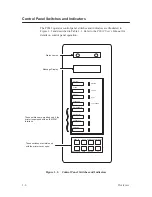
The P9012 operator control panel switches and indicators are illustrated in
Figure 1–2 and described in Table 1–1. Refer to the P9012 User’s Manual for
details on control panel operation.
ON LINE
ON LINE
CLEAR
6/8 LPI
PAPER ADV
CHECK
8 LPI
VFU LOADED
MENU UP
MENU DOWN
NEXT
PREV
RUN/STOP
ENTER
F/L
PRINT MODE
HOLD ENABLE
REPRINT PA1
CANCEL PA2
ALT MODE
These switches are provided only if the
printer is equipped with an IBM 3287
interface.
These switches are visible only
with the printer cover open.
Message Display
Status Lamps
Figure 1–2. Control Panel Switches and Indicators
Summary of Contents for P9012
Page 1: ...P N 132305 001 Rev E P9012 Multifunction Line Printer...
Page 49: ...2 31 Principles of Operation Power Supply PCBAs 1 3 SHORT OPEN Figure 2 21 Power Supply PCBA...
Page 58: ...2 40 Principles of Operation...
Page 84: ...4 18 Troubleshooting...
Page 118: ...5 34 Alignments and Adjustments...
Page 203: ...6 85 Replacement Procedures This page intentionally left blank...
Page 214: ...6 96 Replacement Procedures...
Page 236: ...A 22 Power Paper Stacker Maintenance...
Page 246: ...D 2 Torque Table...
Page 254: ...Index 6...
Page 255: ......
Page 256: ...132305 001 Rev E...

