2–28
Principles of Operation
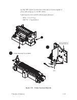
Hammer Bank and Shuttle Mechanics/MPU
(Figure 2–20)
Hammer Bank Assembly/Shuttle
Operation of the hammer bank and shuttle is described on page 2–5.
Magnetic Pickup Unit (MPU)
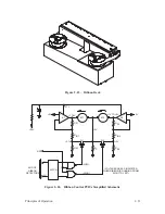
Printing is synchronized with shuttle movement by the magnetic pickup
(MPU) signal. The magnetic pickup, located next to the flywheel timing disk,
is so oriented that timing signals relate precisely to the shuttle position.
Variations in magnetic reluctance are sensed by the magnetic pickup from
apertures on the timing disk as it rotates, generating SYNC pulses. Two
aperture locations at opposite ends of the disk are of double width (material
between two adjacent apertures is removed). These double width apertures
separate the 284 single width apertures into two groups and generate a
RESYNC signal coincident with the shuttle starting to move from left to
right.
Full rotation of the disk provides eight printing periods and four back and
forth shuttle cycles. Each printing period is followed by a turnaround period
when the shuttle movement is reversed, paper is advanced 0.0139 inches, and
no printing occurs.
The SYNC pulses are distributed to timers on the MCU.
The SYNC signal performs the following functions:
•
Signals the MCU to load the hammer driver shift register for the next
hammer firing.
•
Activates all hammers armed with a logic “1” during the previous load of
the hammer driver shift register by generating the NHCK signal.
•
Initiates two time out periods which control the upper drive (NUD) and
the hammer reset signal (HRS). These signals activate and reset hammer
driver circuits previously activated by SYNC.
In the generation of SYNC and RESYNC signals, the roughly sinusoidal
output of the magnetic pickup is amplified and converted to a TTL
compatible square pulse by a circuit on the mechanism driver PCBA. The
Summary of Contents for P9012
Page 1: ...P N 132305 001 Rev E P9012 Multifunction Line Printer...
Page 49: ...2 31 Principles of Operation Power Supply PCBAs 1 3 SHORT OPEN Figure 2 21 Power Supply PCBA...
Page 58: ...2 40 Principles of Operation...
Page 84: ...4 18 Troubleshooting...
Page 118: ...5 34 Alignments and Adjustments...
Page 203: ...6 85 Replacement Procedures This page intentionally left blank...
Page 214: ...6 96 Replacement Procedures...
Page 236: ...A 22 Power Paper Stacker Maintenance...
Page 246: ...D 2 Torque Table...
Page 254: ...Index 6...
Page 255: ......
Page 256: ...132305 001 Rev E...

